Locomotive waste heat recovery system and related methods

a waste heat recovery and locomotive technology, applied in the direction of locomotives, machines/engines, transportation and packaging, etc., can solve the problems of frequent battery replacement, frequent battery replacement, and disruption of operations, and achieve the effect of preventing a substantial drainage of stored power

Inactive Publication Date: 2020-06-18
FILIPPONE CLAUDIO
View PDF0 Cites 2 Cited by
  • Summary
  • Abstract
  • Description
  • Claims
  • Application Information

AI Technical Summary

Benefits of technology

[0016]According to one exemplary embodiment, the converted electrical energy may be conditioned to supply power to selected electrical loads and charge the auxiliary battery to store the converted electrical energy for utilization when the locomotive engine is shut down by, for example, the AESS system and the selected electrical loads are required to remain actively powered for prolonged time periods. For example, when the locomotive engine is shut down by, for example, actuation of the AESS system, and the locomotive crew is still operating the locomotive in the cabin and / or awaiting for the locomotive to be dispatched, the locomotive waste heat recovery system of the present disclosure may switch the power source for one or more selected electrical loads from the locomotive battery to the auxiliary battery, such that the electrical energy stored in the auxiliary battery can be distributed to the selected electrical loads. As a result, the locomotive battery can be decoupled from these electrical loads during this shutdown condition, thereby preventing a substantial drainage of stored power therein during this shutdown condition.
[0017]According to another exemplary aspect, a locomotive waste heat recovery system consistent with the present disclosure may supply battery charging power to an electronic system coupled to the auxiliary battery and regulated by an auxiliary charging regulator while the locomotive engine is operating and thermal energy from the locomotive engine is converted into electricity. When the auxiliary battery is charged, and the locomotive engine is still operating at power and producing waste thermal energy, the auxiliary charging regulator, in conjunction with a load distribution system, may reconfigure the converted electric power so as to supply conditioned electrical power to various electrical loads or hotel loads. For example, as the AESS system actuates and maintains the locomotive engine in a shutdown condition, the auxiliary battery that is configured to provide adequate power rating or capacity for a desired amount of time, can supply electric power to various electrical loads for the selected amount of time, while preserving the locomotive battery, which remains adequately charged to ensure sufficient stored power to activate the engine starting circuit (e.g., a locomotive cranking system) and re-start the locomotive engine, even after prolonged engine shutdown actuated by the AESS system.

Problems solved by technology

As a result of prolonged AESS activation, the locomotive battery may undergo deep charge and discharge cycles and rapidly become unable to perform its intended function, thus inducing operational disruptions as the locomotive engine becomes unable to start, therefore causing frequent battery replacements.
However, as the charge-discharge cycle imposed by locomotive operations is rarely optimal for the locomotive battery, the battery life is significantly reduced even when supercapacitors and additional batteries are coupled to the locomotive battery.
However, as the locomotive crew can override the shutting down of battery-draining equipment, the problem of deep locomotive battery discharges and damages persists, thus inducing frequent battery replacements and disruption of operations.
When the locomotive battery becomes excessively discharged, the remaining battery energy may be insufficient to start the locomotive engine and induce operational disruptions, which increase the locomotive operational costs.
Furthermore, when the locomotive battery undergoes repeated deep discharges, its capacity to store electrical energy reduces and negatively impacts the battery's life-span.
These operational conditions force early replacement of the locomotive battery and thereby increase equipment and operational costs.

Method used


Image

  • Locomotive waste heat recovery system and related methods
  • Locomotive waste heat recovery system and related methods
  • Locomotive waste heat recovery system and related methods

Examples


Embodiment Construction

[0028]Reference will now be made in detail to the exemplary embodiments consistent with the present invention, examples of which are illustrated in the accompanying drawings. Wherever possible, the same reference numbers will be used throughout the drawings to refer to the same or like parts.

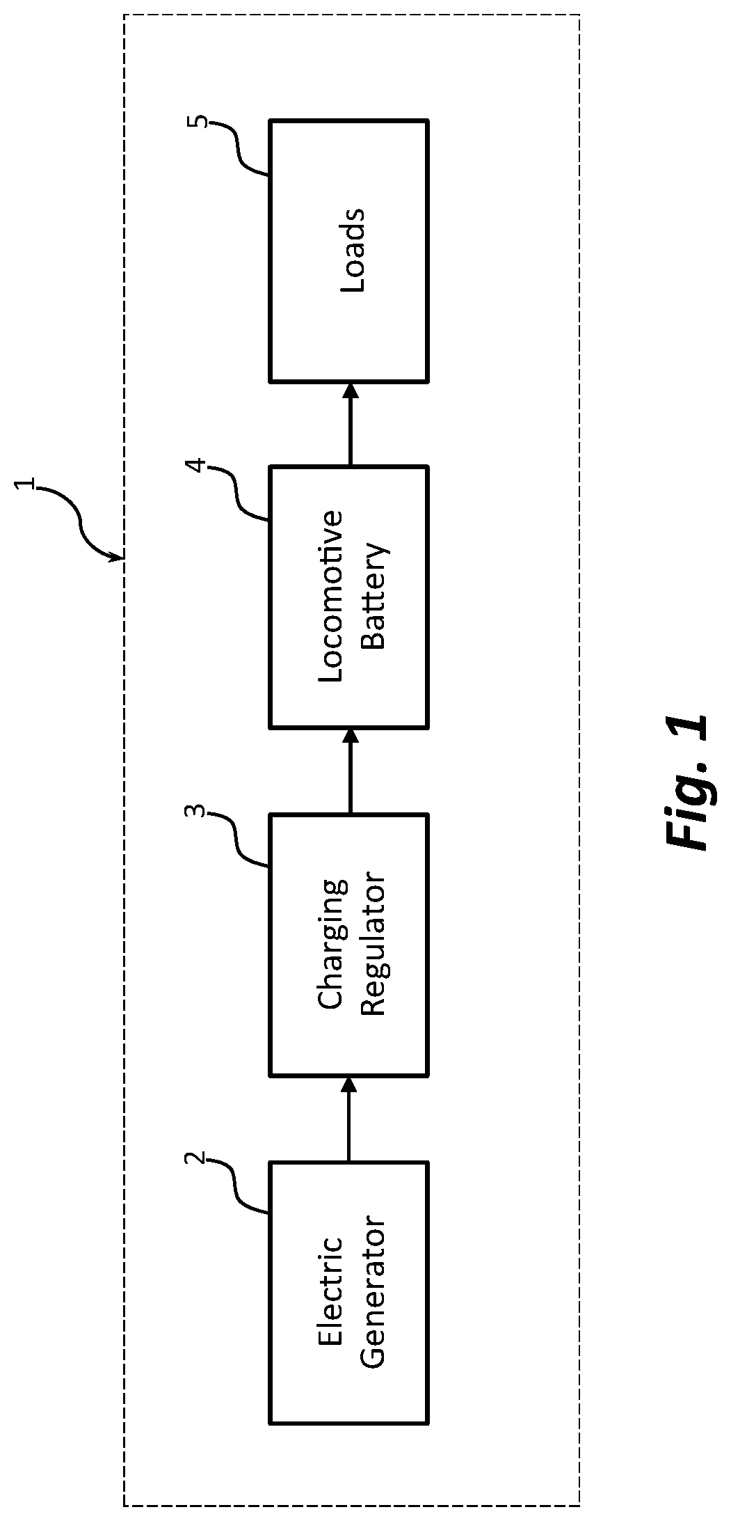
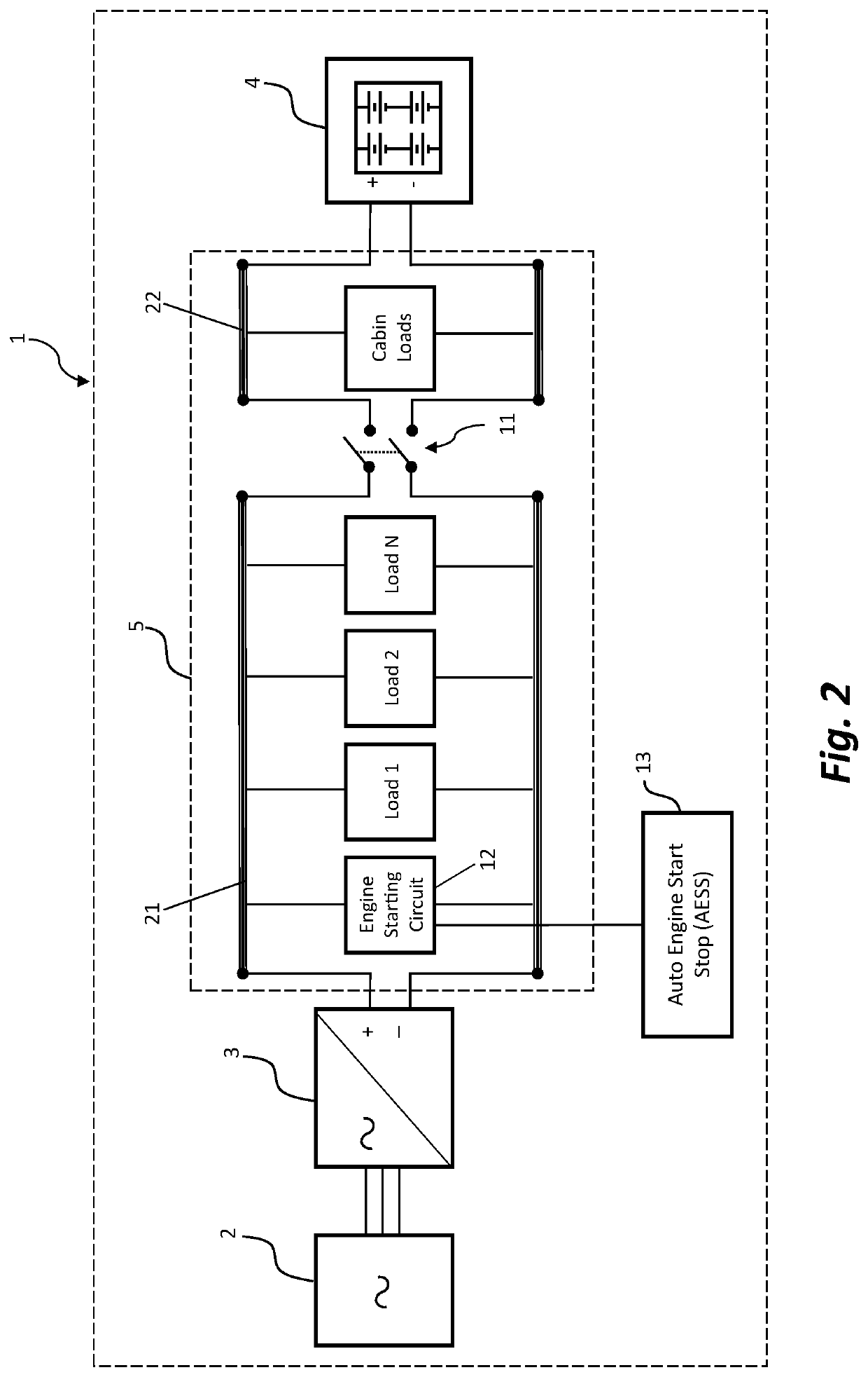
[0029]FIG. 1 is a schematic illustration of a locomotive electrical system 1 for supplying power to a locomotive battery 4 and various electrical loads 5, according to an exemplary embodiment of the present disclosure. FIG. 2 is a functional electrical diagram of the locomotive electrical system 1 of FIG. 1 with details of the locomotive power bus for supplying power to certain locomotive electrical loads and the operations of an AESS system 13.

[0030]As shown in FIGS. 1 and 2, locomotive electrical system 1 may include an electric generator 2, a charging regulator 3, locomotive battery 4, and various electrical loads 5. Locomotive electrical system 1 supplies electrical power to various locomoti...


PUM


Abstract

Various embodiments of a locomotive waste heat recovery system for charging an auxiliary battery, independent of the locomotive electric generator, are disclosed. The auxiliary battery is charged by a locomotive waste heat recovery system to supplement and supply the electric power normally provided by the locomotive battery during a shutdown condition caused by a locomotive auto engine start stop (AESS) system. The auxiliary battery is charged by recovery and conversion of waste thermal energy during locomotive engine operations, and its stored electric power is utilized to supply selected electrical loads during a prolonged engine shutdown condition. Accordingly, the locomotive battery can preserve its stored power to be exclusively utilized for locomotive engine start, which may decrease operational disruptions and increase the life of the locomotive battery, and thereby reducing the overall operating costs associated with the battery maintenance efforts.

Description

[0001]This application claims priority to U.S. Provisional Application No. 62 / 546,548, filed Aug. 16, 2017, which is incorporated herein by reference.FIELD OF INVENTION[0002]The present disclosure relates generally to systems and methods for waste heat recovery. More specifically, particular embodiments of the present disclosure relate to locomotive waste heat recovery systems (L-WHRS), and related methods, configured to charge auxiliary batteries for use in locomotives.DESCRIPTION OF RELATED ART[0003]Technologies to reduce locomotive idling and pollutant emissions, while increasing fuel savings, often focus on improving fuel management through better control of fuel injection and optimizing the operational procedures for the auto engine start stop (AESS) systems. As the locomotive engine is automatically shut down during prolonged idling operations, selected locomotive electrical loads remain on to ensure vital equipment readiness (e.g., braking system) with electric power supplied...

Claims


Application Information

Patent Timeline
Patent Type & Authority Applications(United States)
IPC IPC(8): B61C17/06F02G5/00H02J7/14H02J7/02
CPCH02J7/02B61C7/04F02G5/00H02J7/1423B61C17/06B60L1/00Y02T10/12Y02T30/00H02J7/14
Inventor FILIPPONE, CLAUDIO
Owner FILIPPONE CLAUDIO
Why Eureka
Try Eureka