Soil recycling mechanism of flower transplanting machine

A technology of recycling mechanism and transplanting machine, which is applied in the filling, cultivation, gardening and other directions of flowerpots, can solve the problems of falling on the ground, the soil is easy to fall off, and economic losses, so as to avoid the loss of soil and reduce the The effect of artificial labor and economic loss reduction

Active Publication Date: 2019-10-22
连云港人与人环保科技有限公司
View PDF6 Cites 1 Cited by
  • Summary
  • Abstract
  • Description
  • Claims
  • Application Information

AI Technical Summary

Problems solved by technology

At present, flower transplanting is generally done manually. When manually transplanting by workers, the original soil of the flower roots is prone to fall off, and the fallen soil will fall on the ground, thereby increasing the workman's cleaning labor. Planting may damage the roots of the flowers, resulting in the restriction of the growth of the flowers after transplanting. In severe cases, the flowers will die, causing economic losses, and the cost of manual transplanting is high and the efficiency is low.

Method used


Image

  • Soil recycling mechanism of flower transplanting machine
  • Soil recycling mechanism of flower transplanting machine
  • Soil recycling mechanism of flower transplanting machine

Examples


Embodiment 1

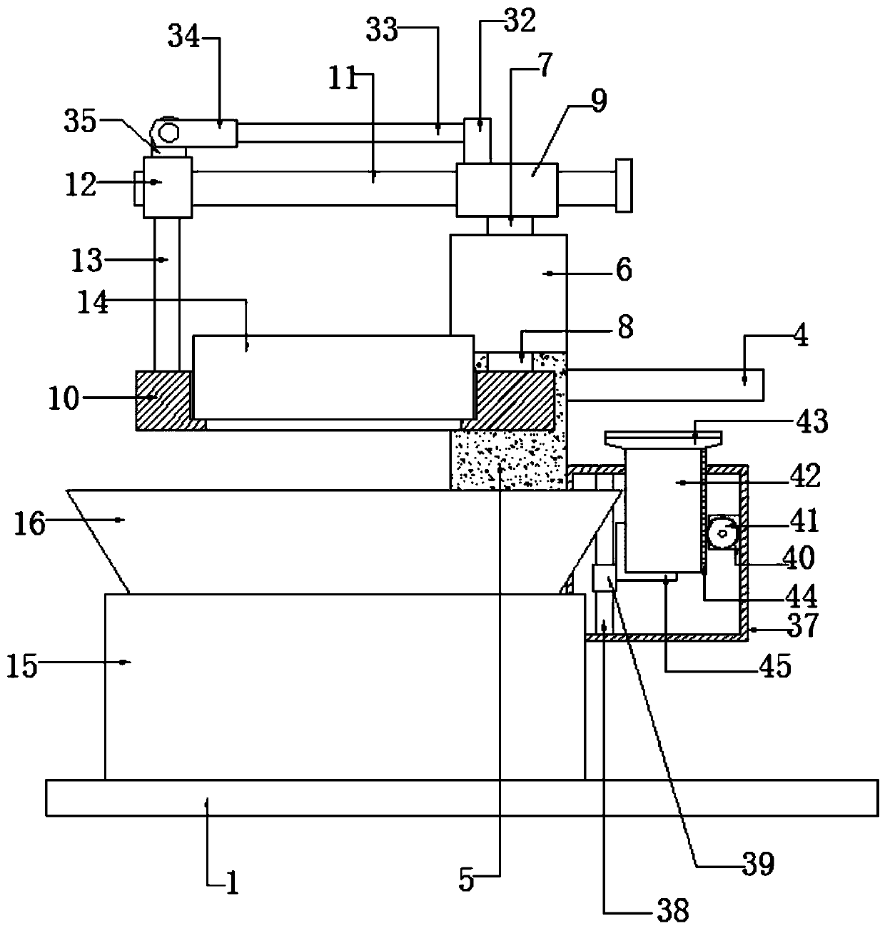
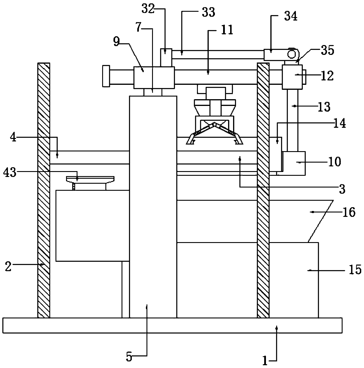
[0031] Embodiment one, such as Figure 1-3 As shown, a soil recovery mechanism of a flower transplanting machine according to an embodiment of the present invention includes a base plate 1, a frame 2 is provided on both sides of the top of the base plate 1, and two parallel frames are arranged between the frame 2. The first conveyor belt 3 and the second conveyor belt 4 are set, a support column 5 is arranged between the first conveyor belt 3 and the second conveyor belt 4, and a bidirectional motor 6 is installed on the top of the support column 5 on the front side. The two ends of bidirectional motor 6 are respectively provided with rotating shaft one 7 and rotating shaft two 8, and the ends of described rotating shaft one 7 and described rotating shaft two 8 are respectively provided with fixed block one 9 and object plate 10, and the ends of described rotating shaft one 9 and The middle part runs through a connecting rod one 11, and the end of the connecting rod one 11 and...

Embodiment 2

[0032] Embodiment two, such as figure 1As shown, the storage board 10 is located below the sides of the first conveyor belt 3 and the second conveyor belt 4 , and the top opening diameter of the material guide funnel 16 is larger than the bottom cross-sectional size of the storage board 10 .

Embodiment 3

[0033] Embodiment three, such as figure 1 As shown, the top of the fixed block one 9 and one end close to the fixed block three 12 are provided with a fixed block two 32, and the fixed block two 32 and the side corresponding to the fixed block three 12 are provided with a connecting rod two 33, the end of the connecting rod 2 33 and away from the fixed block 2 32 is provided with a clamping plate 34, and the end of the clamping plate 34 and away from the connecting rod 2 33 is provided with a clamping plate 1 35, the The top of the fixed block three 12 is provided with clamping plate two 36, and the top of the clamping plate two 36 is connected and fixed with the end of the clamping plate one 35 through a shaft, wherein the connecting rod one 11 is away from the fixed One end of block three 12 is provided with limit block.


PUM


Abstract

The invention discloses a soil recycling mechanism of a flower transplanting machine. The soil recycling mechanism comprises a bottom plate; racks are arranged on two sides of the top of the bottom plate. First and second conveyer belts arranged in parallel are arranged between the racks. A support post is arranged between the first conveyer belt and the second conveyer belt; a bidirectional motoris mounted at the top of one side of the front of the support post; two ends of the bidirectional motor are provided with a spindle I and a spindle II respectively; the end of the spindle I and the second of the spindle II are provided with a fixing block I and a holding plate respectively; a connection bar I penetrates the middle of the fixing block I; the end of the connection bar far away fromthe fixing block I is sleeved with a fixing block III; a support bar is arranged at the bottom of the fixing block III; the bottom of the support bar is fixed to one end of the top of the holding plate. The soil recycling mechanism has the advantages that loss of soil at flower roots during transplanting is avoided, working efficiency is improved effectively, and survival rate of flowering plantsafter planting is increased.

Description

technical field [0001] The invention relates to the technical field of planting equipment, in particular to a soil recovery mechanism of a flower transplanter. Background technique [0002] Flowers refer to herbaceous plants with ornamental value, such as clivia, narcissus, chrysanthemum, cockscomb, cactus, etc. In recent years, with the construction of landscape cities and the improvement of people's living taste, the demand for flowers is increasing. The current flowers are planted in batches. In order to save costs in the future, smaller flower pots will be used in the early stage of flower planting to reduce the space occupied and facilitate management. After the flowers grow to a certain extent, the flowers need to be transplanted to larger pots. Put it on the flower pot, so that the flowers can grow better. At present, flower transplanting is generally done manually. When manually transplanting by workers, the original soil of the flower roots is prone to fall off, a...

Claims


Application Information

Patent Timeline
Patent Type & Authority Applications(China)
IPC IPC(8): A01G9/08
CPCA01G9/081A01G9/083A01G9/086
Inventor 战思宇
Owner 连云港人与人环保科技有限公司
Why Eureka
Try Eureka