Construction method of inclined throwing support protector and inclined throwing support protector

A construction method and technology of oblique throwing, which is applied in excavation, infrastructure engineering, construction, etc., can solve the problems of destructive impact and high risk of enclosure walls, and achieve the advantages of easy demolition and recycling, reduced production costs, fast and safe construction Effect

Pending Publication Date: 2019-10-22
麦廊建设有限公司
View PDF1 Cites 1 Cited by
  • Summary
  • Abstract
  • Description
  • Claims
  • Application Information

AI Technical Summary

Problems solved by technology

However, in the process of excavating and making corbel support points, the excavation itself may have a destructive effect on the enclosure wall, so the risk is extremely high

Method used


Image

  • Construction method of inclined throwing support protector and inclined throwing support protector
  • Construction method of inclined throwing support protector and inclined throwing support protector
  • Construction method of inclined throwing support protector and inclined throwing support protector

Examples


Embodiment 1

[0037] Embodiment 1, a construction method of oblique throw support, comprising:

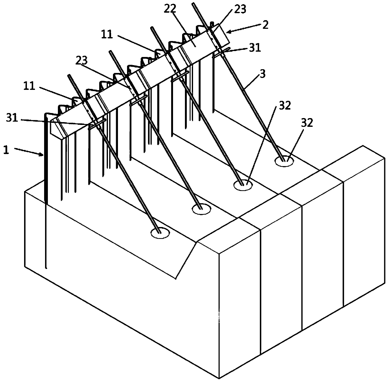
[0038] Step 1, fixing the purlin structure 2 along the upper edge of the retaining wall 1, and the length of the purlin structure 2 extends along the extending direction of the retaining wall 1;

[0039] Step 2: Install the oblique brace 3 obliquely on the same side on the purlin structure 2, and form a guide channel 21 on the purlin structure 2 that allows the oblique brace 3 to move along the only linear direction, allowing the oblique brace 3 to move along its length direction Moving relative to the purlin structure 2, a right angle a or an acute angle a is formed between the diagonal brace 3 and the retaining wall 1, and the right angle a can correspond to a slope bank with a relatively steep angle, that is, the diagonal brace 3 is horizontally braced on the slope bank; the acute angle a can correspond to a relatively gentle slope bank or flat ground, such as the inclined throw support 3 alo...

Embodiment 2

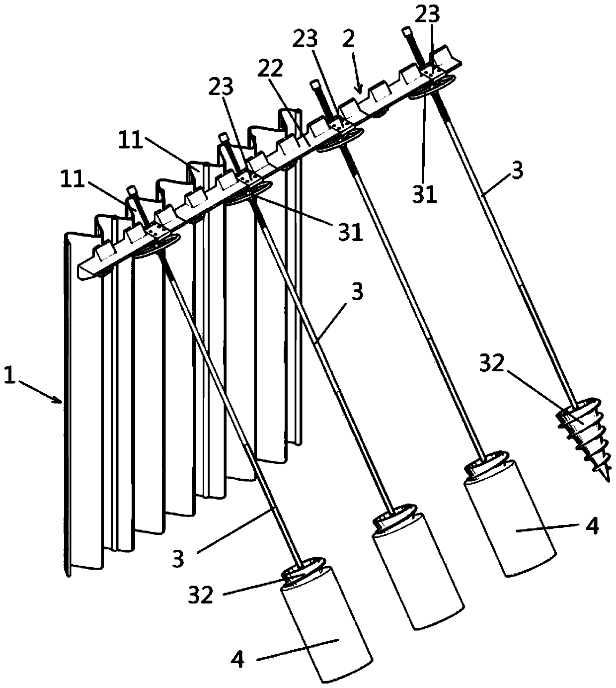
[0049] Embodiment two, as attached figure 2 As shown, the main difference between the second embodiment and the first embodiment is that the structure of the diagonal support leg 32 is different. Tapping legs, pointed self-tapping legs have self-tapping threads that can be easily drilled into the soil when rotating, that is, the diagonal throwing brace 3 is inserted or screwed into the soil relative to the purlin structure 2 along its length direction. The threaded fit between the oblique brace 3 and the purlin structure 2 is similar to the use of the screw-in type to move the oblique brace 3 up and down. Similarly, if the soil is loose, it can be done before the oblique brace 3 enters the soil, and after entering the soil It is also possible to use a cement high-pressure rotary grouting machine to pour concrete or cement slurry into the soil corresponding to the slanting support feet 32 ​​to form the pier 4, so that the pointed self-tapping support feet and the pier 4 thread...

Embodiment 3

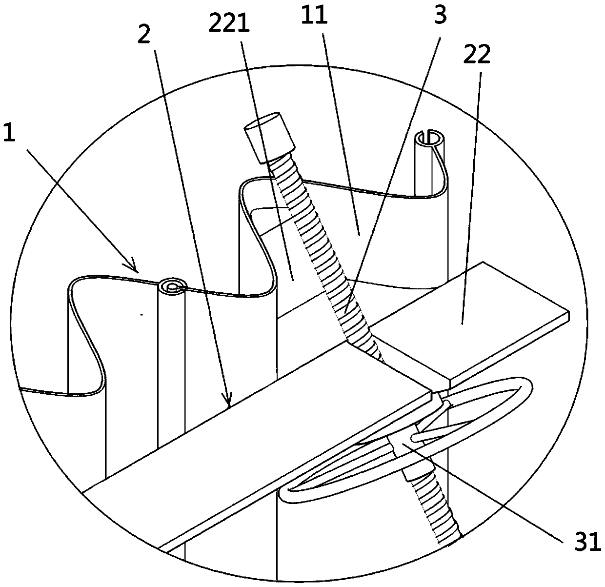
[0050] Embodiment three, as attached image 3 As shown, the difference between Embodiment 3 and Embodiments 1 and 2 is that the purlin body 22 has a protruding purlin reinforcement part 221, and when the purlin structure 2 is fixed along the upper side of the enclosure wall 1, the purlin reinforcement is fixed. part 221 , the purlin reinforcement part 221 is inserted into the groove 11 and fixedly connected with the enclosure wall 1 . Further, the installation between the purlin structure 2 and the retaining wall 1 is firm and stable. The purlin body 22 is provided with a groove for accommodating the oblique throwing brace 3, rather than a guiding channel with the only direction. Diagonal cast support 3 can be removed and inserted in the groove. However, due to the conflict between the limit lock 31 and the purlin body 22 and the pressure from the outside of the retaining wall 1 , the diagonal throw brace 3 can be stably inserted in the groove.


PUM


Abstract

The invention discloses a construction method of an inclined throwing support protector and the inclined throwing support protector. The inclined throwing support protector comprises a purlin structure fixed at the upper edge part of a surrounding wall, and an inclined throwing support movably/detachably arranged on the purlin structure; a locking mechanism for locking the purlin structure and theinclined throwing support is arranged between the purlin structure and the inclined throwing support; and inclined support legs are arranged at the lower end part of the inclined throwing support. After the purlin structure is mounted on the surrounding wall, the inclined throwing support is connected to soil through inclining to one side of the surrounding wall on the purlin structure; the lowerend part of the inclined throwing support forms a support point on the soil; and the inclined throwing support and the purlin structure are locked. The excavation is not needed during installing of the inclined throwing support, so that the construction is quick and safe, the dismantling and the recovery are convenient, and the production cost is greatly reduced.

Description

technical field [0001] The invention relates to a construction method of an oblique cast support and the oblique cast support. Background technique [0002] With the acceleration of the urbanization process in our country, the development and utilization of underground space has developed rapidly, and foundation pit engineering has become more and more common. Therefore, the structure and implementation technology of foundation pit enclosure walls have continued to develop. Foundation pit engineering is a temporary enclosure that only works during the excavation phase of the basement. Therefore, it is generally necessary to comprehensively consider factors such as the surrounding environment, structural safety, project cost, construction convenience, and construction period. [0003] Foundation pit enclosure works include gravity type, cable-stayed type, parallel-braced type, inclined throw-braced type, etc. Among them, the oblique throwing type is a very reliable foundatio...

Claims


Application Information

Patent Timeline
Patent Type & Authority Applications(China)
IPC IPC(8): E02D17/04
CPCE02D17/04
Inventor 吴健丁毅强吴芳缪拥军沈磊王鑫孙亮吴小虎陈铖
Owner 麦廊建设有限公司
Why Eureka
Try Eureka