Steam compression equipment

A technology for compressing equipment and steam, applied in the field of fluid compression, can solve problems such as the failure of vapor compression equipment, limit the product stability of vapor compression equipment, reduce the working efficiency of vapor compression equipment, etc., and achieve the effect of improving product stability.

Inactive Publication Date: 2019-10-22
NANTONG DART POLLRICH FAN
View PDF6 Cites 0 Cited by
  • Summary
  • Abstract
  • Description
  • Claims
  • Application Information

AI Technical Summary

Problems solved by technology

The tight connection between the impeller and the main shaft is the premise and key to the safe operation of vapor compression equipment. If there is a gap between the impeller and the main shaft during high-speed rotation, the fluid medium will leak from the compression chamber, reducing the vapor compression The efficiency of the equipment, and even make the vapor compression equipment completely ineffective, which limits the product stability of the vapor compression equipment

Method used


Image

  • Steam compression equipment
  • Steam compression equipment
  • Steam compression equipment

Examples


Embodiment Construction

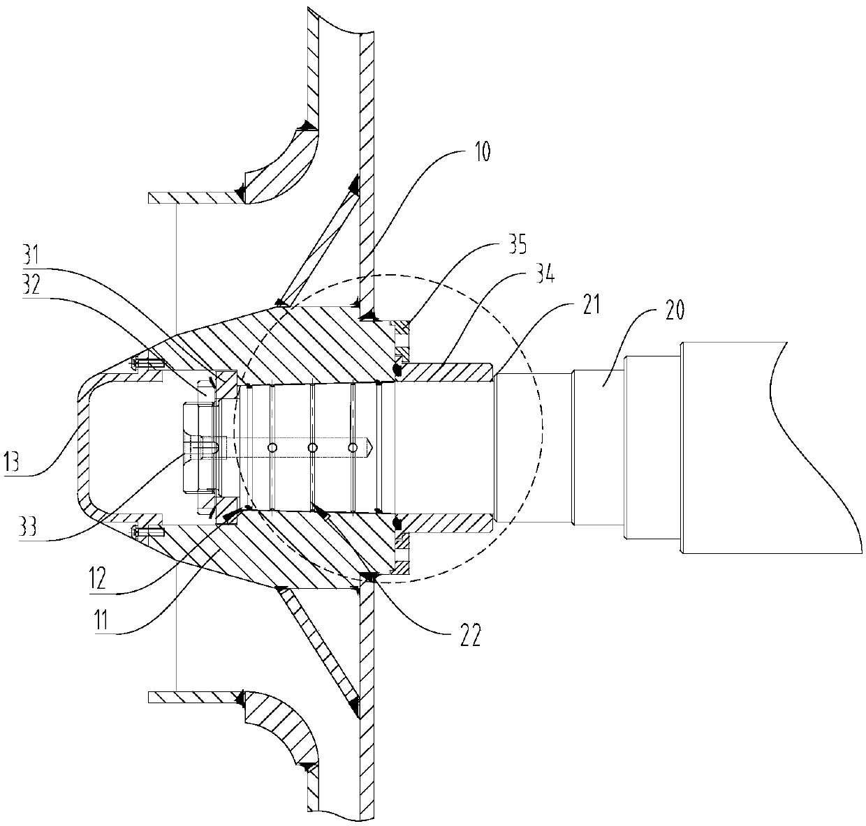
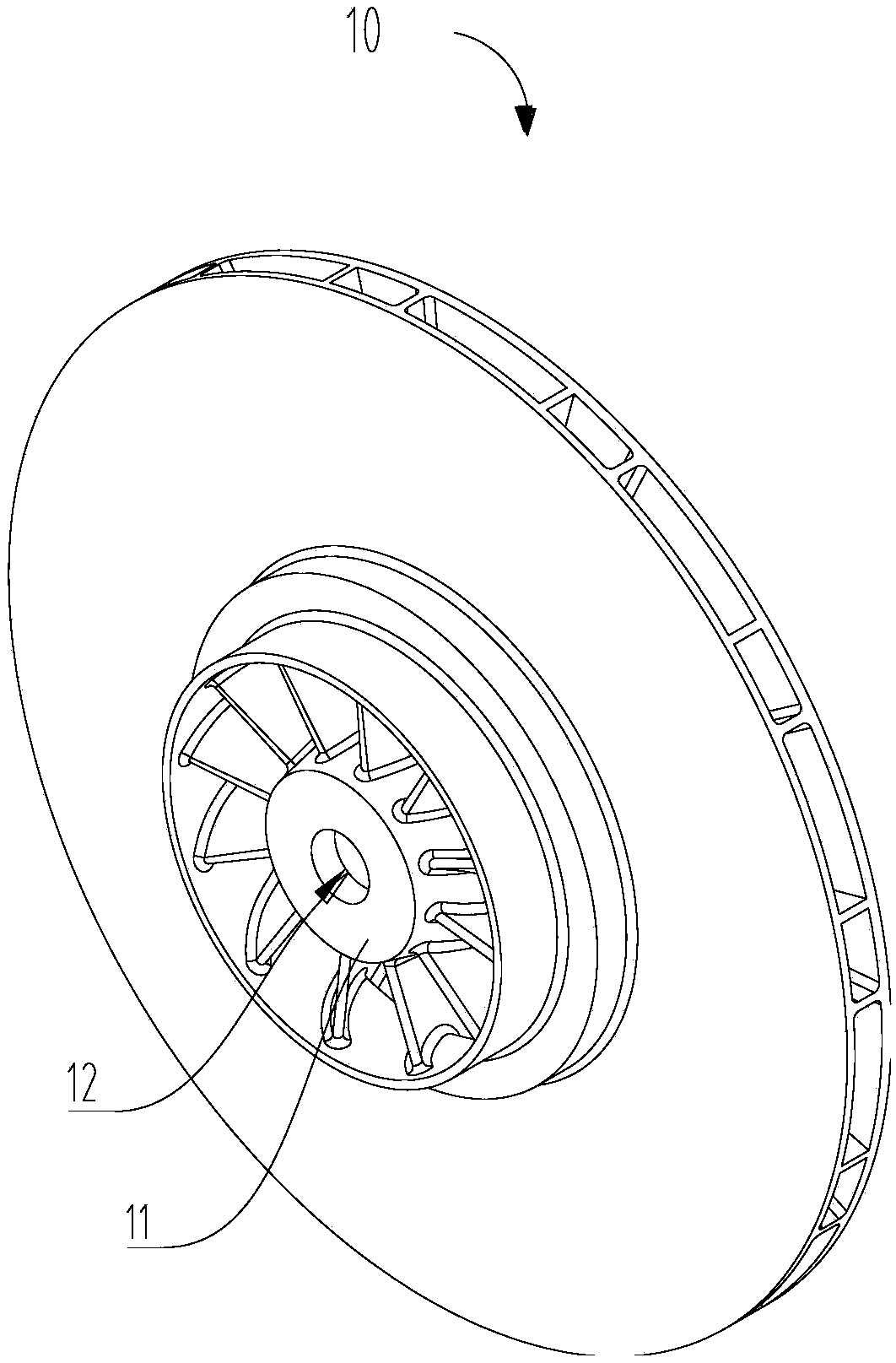
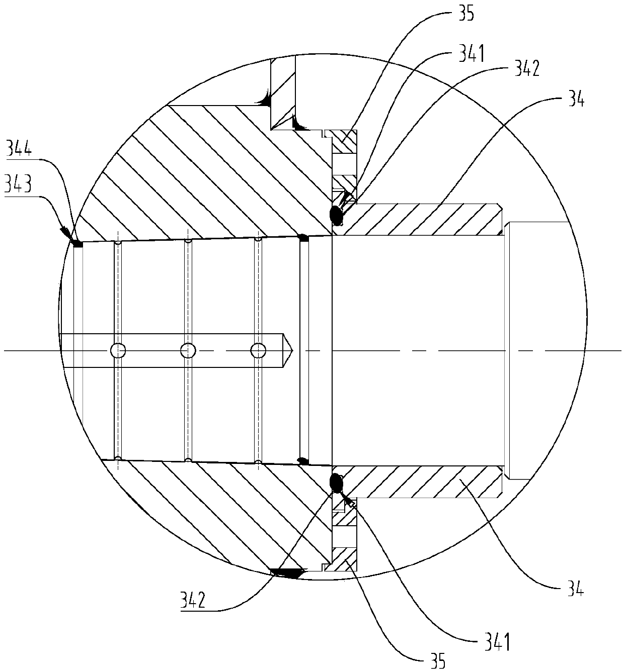
[0022] The following will clearly and completely describe the technical solutions in the embodiments of the present invention with reference to the accompanying drawings in the embodiments of the present invention. Obviously, the described embodiments are only some, not all, embodiments of the present invention. Based on the embodiments of the present invention, all other embodiments obtained by persons of ordinary skill in the art without making creative efforts belong to the protection scope of the present invention.

[0023] It should be noted that when a component is said to be "mounted on" another component, it may be directly mounted on another component or there may be an intervening component. When a component is said to be "set on" another component, it may be set directly on the other component or there may be an intervening component at the same time. When a component is said to be "fixed" to another component, it may be directly fixed to the other component or ther...


PUM


Abstract

The invention provides steam compression equipment. The steam compression equipment comprises an impeller and a main shaft, the impeller is arranged on the main shaft in a penetrating mode, a shaft sleeve is arranged on the main shaft, one end of the shaft sleeve abuts against the impeller, the other end of the shaft sleeve abuts against the main shaft, an end face sealing groove is formed in theend face, in contact with the impeller, of the shaft sleeve, an end face sealing ring is accommodated in the end face sealing groove, axial sealing grooves are formed in the portion, penetrating through a through hole, of the main shaft, axial sealing rings are accommodated in the axial sealing grooves, the end face sealing ring is used for achieving end face sealing between the impeller and the main shaft, the axial sealing rings are used for achieving axial sealing between the impeller and the main shaft. According to the provided steam compression equipment, fastening sealing connection between the impeller and the main shaft can be achieved so that the fluid media in the impeller cannot leak outwards from a gap between the impeller and the main shaft, and the product stability of the steam compression equipment is improved.

Description

technical field [0001] The invention relates to the technical field of fluid compression, in particular to a vapor compression device. Background technique [0002] Vapor compression equipment is a heat recovery equipment that compresses the secondary steam generated in the evaporation process to increase the pressure and temperature of the secondary steam so that it can re-enter the evaporation cycle. It is widely used in chemical, medical, food concentration, solution Recycling and many other important industrial fields. The tight connection between the impeller and the main shaft is the premise and key to the safe operation of vapor compression equipment. If there is a gap between the impeller and the main shaft during high-speed rotation, the fluid medium will leak from the compression chamber, reducing the vapor compression The working efficiency of the equipment can even make the vapor compression equipment completely ineffective, which limits the product stability of...

Claims


Application Information

Patent Timeline
IPC IPC(8): F04D29/12F04D29/00
CPCF04D29/002F04D29/122
Inventor 邓聪周晓东刘红艳
Owner NANTONG DART POLLRICH FAN
Why Eureka
Try Eureka