Micropump

A micro-pump and fluid channel technology, applied in the direction of pumps, pump components, pump devices, etc., can solve the problems of inability to dissipate, difficult to dissipate heat, and burn out winding stators.

Pending Publication Date: 2019-10-22
深圳市欣普斯科技有限公司
View PDF0 Cites 3 Cited by
  • Summary
  • Abstract
  • Description
  • Claims
  • Application Information

AI Technical Summary

Problems solved by technology

However, when the water pump is actually working, the winding stator is energized to drive the permanent magnet rotor to rotate, the winding stator will generate heat, and the shell of the water pump is a relatively closed structure, it is difficult to completely dissipate the heat generated by the winding stator, and the heat will gradually increase over time. Accumulated on the winding stator, it cannot be removed for a long time or even burns the winding stator, which greatly affects the working life of the winding stator. If an additional heat dissipation module is used, the occupied volume of the overall water pump will be significantly increased

Method used


Image

  • Micropump
  • Micropump
  • Micropump

Examples


Embodiment Construction

[0021] The present application will be described in further detail below in conjunction with the accompanying drawings and specific embodiments. It should be understood that the following exemplary embodiments and descriptions are only used to explain the present invention, not as a limitation to the present invention, and, in the case of no conflict, the embodiments in the application and the features in the embodiments can be combined with each other .

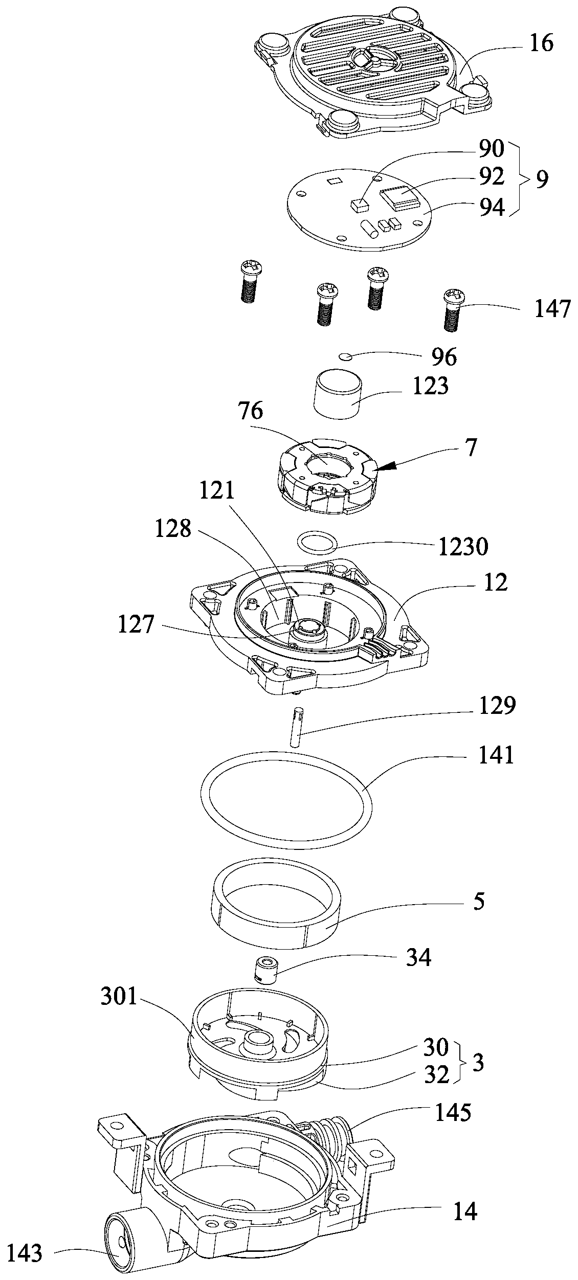
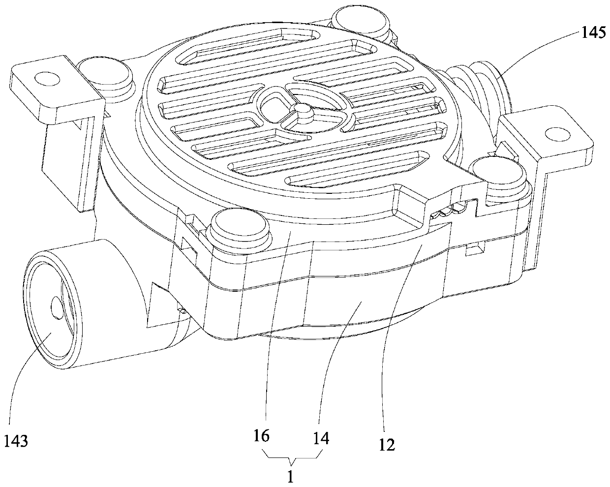
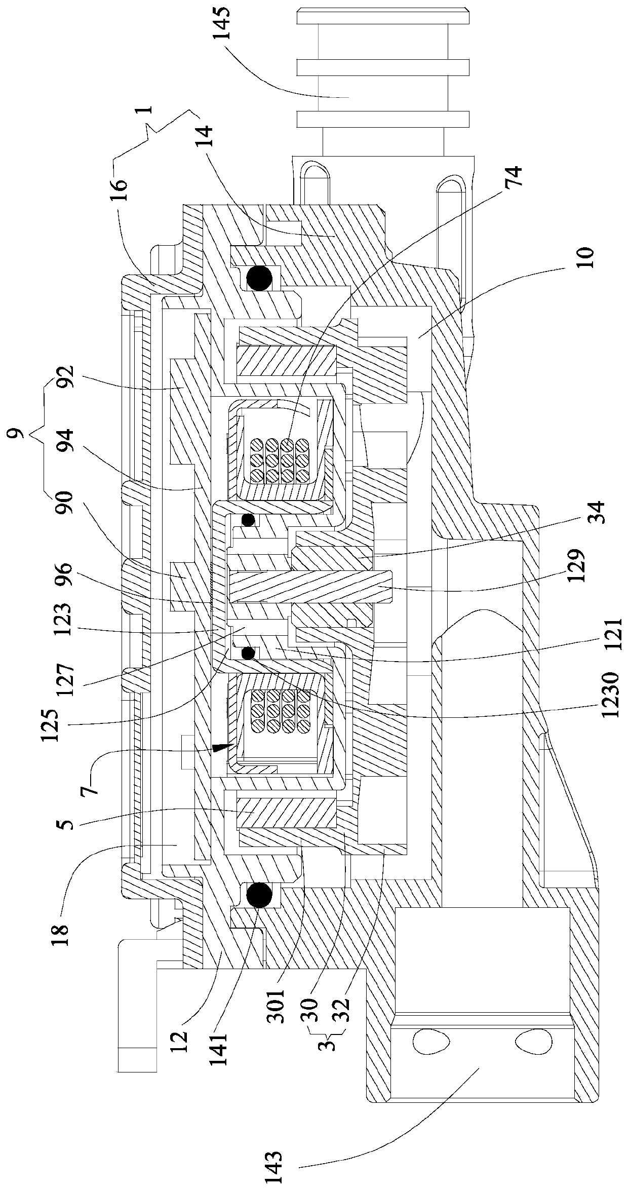
[0022] Such as Figure 1-Figure 3 As shown, the embodiment of the present invention provides a micropump, which includes a casing 1, an impeller 3 installed in the casing 1, a permanent magnet rotor 5 connected to the impeller 3, and a magnetic force generated by electricity to drive the permanent magnet. The winding stator 7 of the rotor 5 is oriented and rotated. The casing 1 is provided with a fluid channel 10 for guiding the flow of the pumped liquid. The impeller 3 is installed in the fluid channel 10, and the winding ...


PUM


Abstract

The embodiment of the invention provides a micropump including a housing, an impeller mounted in the housing, a permanent magnet rotor in transmission connection with the impeller and a winding statorwhich is energized to generate magnetic force to drive the permanent magnet rotor to rotate in an oriented manner; a fluid passage for guiding pumped liquid to flow is formed in the housing, the impeller is mounted in the fluid passage, the winding stator is mounted in the exterior of the fluid passage, at least a part of passage wall of the fluid passage is made of a high heat conduction material, and the winding stator is in tight contact with the outer surface of the channel wall, made of the high heat conduction material, of the fluid passage. By means of the embodiment, the winding stator is in tight contact with the outer surface of the channel wall, made of the high heat conduction material, of the fluid passage, when the micropump works, heat generated by the winding stator is transmitted to the pumped liquid through the passage wall, then the heat is carried away along with directional flow of the pumped liquid, and therefore the heat generated by the winding stator is effectively dissipated, and the winding stator can be maintained at the suitable operating temperature.

Description

technical field [0001] The embodiments of the present invention relate to the technical field of water pumps, in particular to a micro pump. Background technique [0002] Generally, the water pump includes a casing, an impeller installed in the casing, a permanent magnet rotor connected to the impeller, and a winding stator that generates magnetic force to drive the permanent magnet rotor to rotate. However, when the water pump is actually working, the winding stator is energized to drive the permanent magnet rotor to rotate, the winding stator will generate heat, and the shell of the water pump is a relatively closed structure, it is difficult to completely dissipate the heat generated by the winding stator, and the heat will gradually increase over time. Accumulated on the winding stator, it cannot be removed for a long time or even burns the winding stator, which greatly affects the working life of the winding stator. If an additional heat dissipation module is used, the ...

Claims


Application Information

Patent Timeline
Patent Type & Authority Applications(China)
IPC IPC(8): F04D29/58F04D13/06
CPCF04D29/5806F04D29/5893F04D13/0606
Inventor 陈水根李国龙
Owner 深圳市欣普斯科技有限公司
Why Eureka
Try Eureka