Fully-automatic thin oil lubrication system

A thin oil lubrication, fully automatic technology, applied in the direction of engine lubrication, lubricating parts, lubricating oil control valve, etc.

Pending Publication Date: 2019-10-22
南京恒昌包装机械有限公司
View PDF0 Cites 2 Cited by
  • Summary
  • Abstract
  • Description
  • Claims
  • Application Information

AI Technical Summary

Problems solved by technology

[0004] In order to solve the problems existing in the prior art that the capping machine is lubricated with grease, the lubricating effect is poor, and it cannot play the role of cooling and sewage discharge, the present invention proposes a fully automatic thin oil lubrication system, which solves the above technical problems

Method used


Image

  • Fully-automatic thin oil lubrication system
  • Fully-automatic thin oil lubrication system
  • Fully-automatic thin oil lubrication system

Examples


Embodiment Construction

[0028] The content of the present invention will be further described below in conjunction with the accompanying drawings.

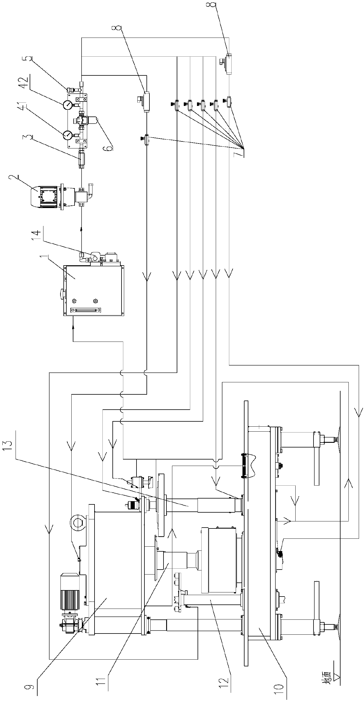
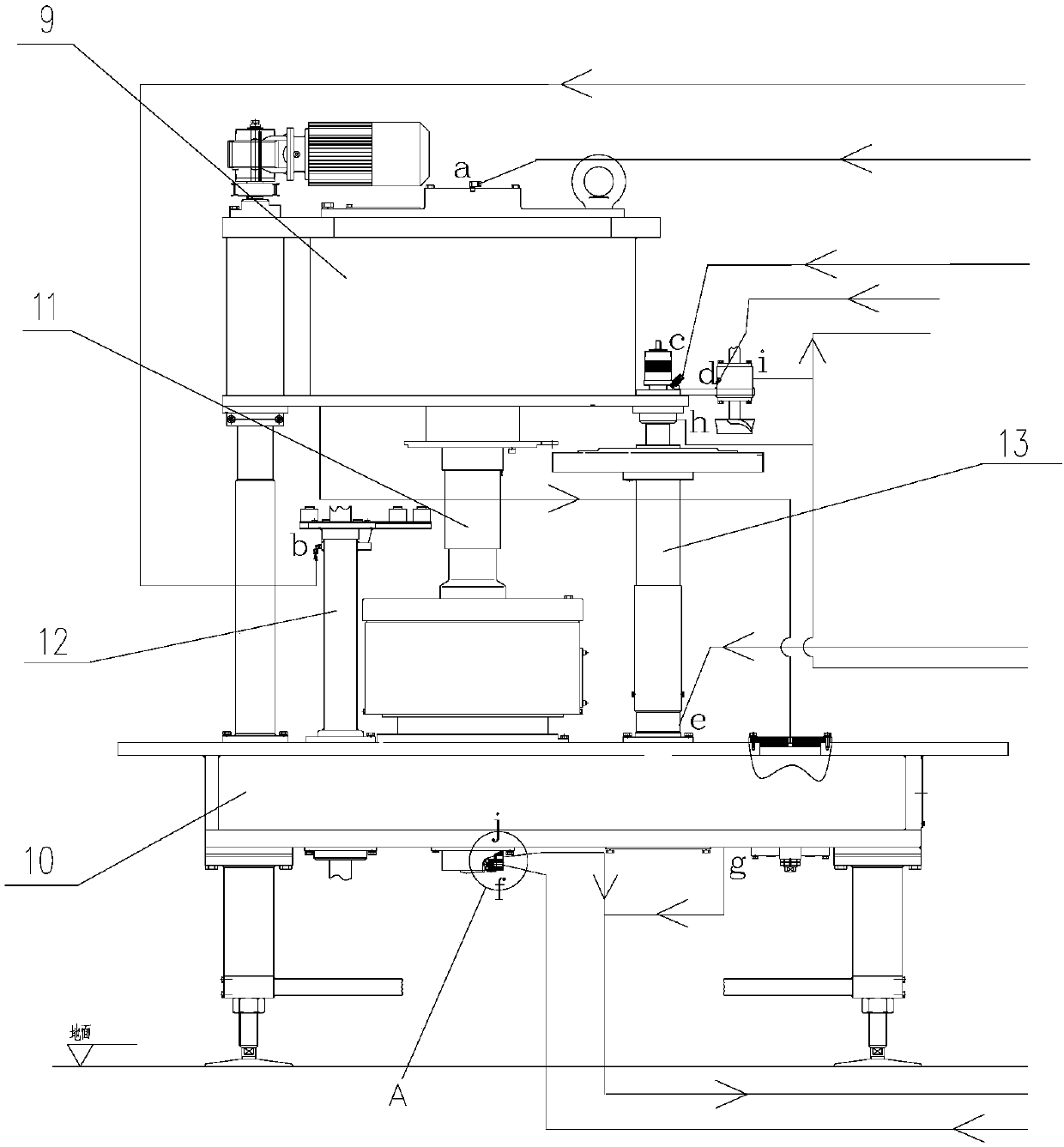
[0029] Such as Figure 1-5 As shown, the present embodiment provides a fully automatic thin oil lubrication system, including an oil tank 1 and a capping machine. The oil tank 1 is filled with thin oil, and the capping machine is provided with an oil inlet, an oil outlet, and an oil passage. The oil tank 1 The pipeline communicates with the capping machine, and the lubricating oil in the oil tank 1 enters the capping machine to lubricate the capping machine.

[0030] The oil tank 1 is used to store the thin oil that plays a lubricating role. The oil tank 1 is provided with a pressure oil port and an oil return port. The pressure oil port of the oil tank 1 communicates with the oil inlet of the capping machine through the oil pump 2. The capping machine The oil outlet communicates with the oil return port of the oil tank 1. The thin oil in the oil tank ...


PUM


Abstract

The invention relates to the field of packaging machinery, in particular to a fully-automatic thin oil lubrication system. The full-automatic thin oil lubrication system supplies oil to a capping machine, and comprises an oil tank and an oil pump, the thin oil is contained in the oil tank, the oil tank communicates with the capping machine, the thin oil in the oil tank is conveyed to an oil inletof the capping machine under the suction effect of the oil pump, and the thin oil enters an oil channel in the capping machine through the oil inlet, and flows in the oil channel and is used for lubricating the capping machine, and finally the thin oil flows back to the oil tank to be recycled through an oil outlet of the capping machine. According to the fully-automatic thin oil lubrication system, the problems that in the prior art, a capping machine adopts grease to lubricate, the lubricating effect is poor, and the effects of cooling and dirt discharging cannot be achieved are solved.

Description

technical field [0001] The invention relates to the field of packaging machinery, in particular to a fully automatic thin oil lubrication system. Background technique [0002] In the can making process, after the flanging of the cylindrical can body is completed, the bottom and cover of the can body need to be sealed to complete the production. The capping machine is a commonly used equipment for back cover and cover. Its basic principle is to use the seaming wheel to roll the surface cover or bottom cover along the contour edge of the tank body to achieve the purpose of sealing. The capping equipment belongs to high-speed operation equipment. The capping equipment needs to cap 800-1200 cans per minute. The capping equipment is a mechanical structure. During use, attention should be paid to the lubrication of the capping equipment, otherwise it will be greatly damaged. affect the service life. [0003] The traditional capping machine does not have a sealed space to provide...

Claims


Application Information

Patent Timeline
Patent Type & Authority Applications(China)
IPC IPC(8): F16N29/04F16N29/02F16N7/36F16N23/00F16N33/00F16N39/06
CPCF16N7/36F16N23/00F16N29/02F16N29/04F16N33/00F16N39/06F16N2250/04
Inventor 吴中军许正荣徐亚春
Owner 南京恒昌包装机械有限公司
Why Eureka
Try Eureka