
Automatic lubrication device arranged between material barrel and plunger chip

An automatic lubrication and material technology, applied in the field of die casting, can solve the problems of complex control and poor lubrication effect, and achieve the effect of improving production efficiency, low cost and simple structure

Active Publication Date: 2016-04-13
辽宁天海津城装备制造有限公司
View PDF7 Cites 1 Cited by
  • Summary
  • Abstract
  • Description
  • Claims
  • Application Information

AI Technical Summary

Problems solved by technology

[0003] In view of this, the present invention aims to propose an automatic lubricating device between the material cylinder and the punch to solve the problems of poor lubricating effect and complicated control in the prior art

Method used


Image

  • Automatic lubrication device arranged between material barrel and plunger chip
  • Automatic lubrication device arranged between material barrel and plunger chip
  • Automatic lubrication device arranged between material barrel and plunger chip

Examples


Embodiment Construction

[0020] It should be noted that, in the case of no conflict, the embodiments of the present invention and the features in the embodiments can be combined with each other.

[0021] In describing the present invention, it should be understood that the terms "center", "longitudinal", "transverse", "upper", "lower", "front", "rear", "left", "right", " The orientations or positional relationships indicated by "vertical", "horizontal", "top", "bottom", "inner" and "outer" are based on the orientations or positional relationships shown in the drawings, and are only for the convenience of describing the present invention and Simplified descriptions, rather than indicating or implying that the device or element referred to must have a particular orientation, be constructed and operate in a particular orientation, and thus should not be construed as limiting the invention. In addition, the terms "first", "second", etc. are used for descriptive purposes only, and should not be interpreted...


PUM


Abstract

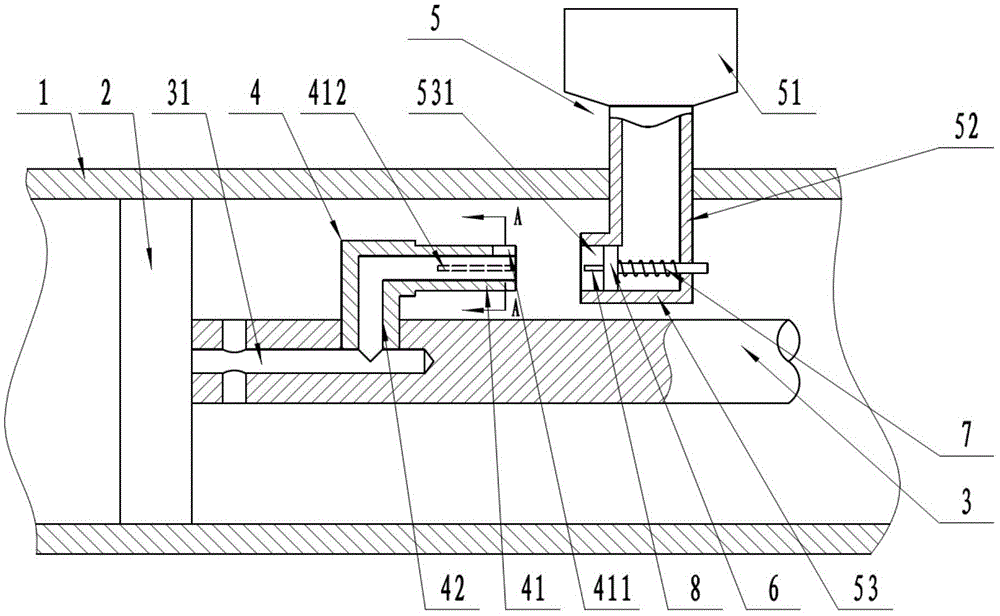
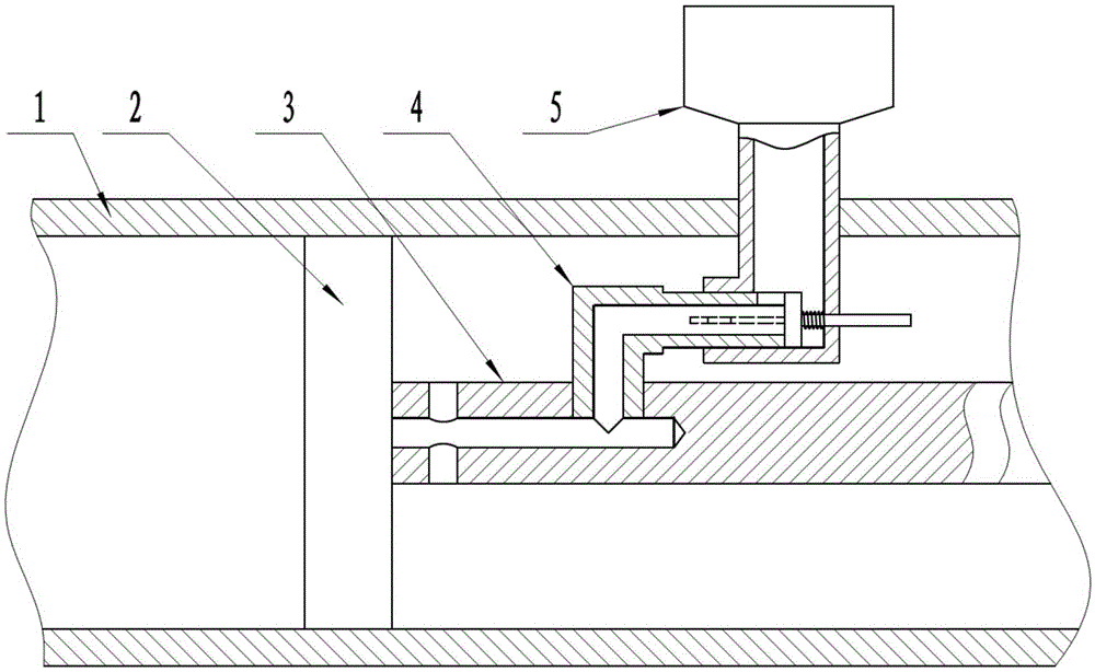
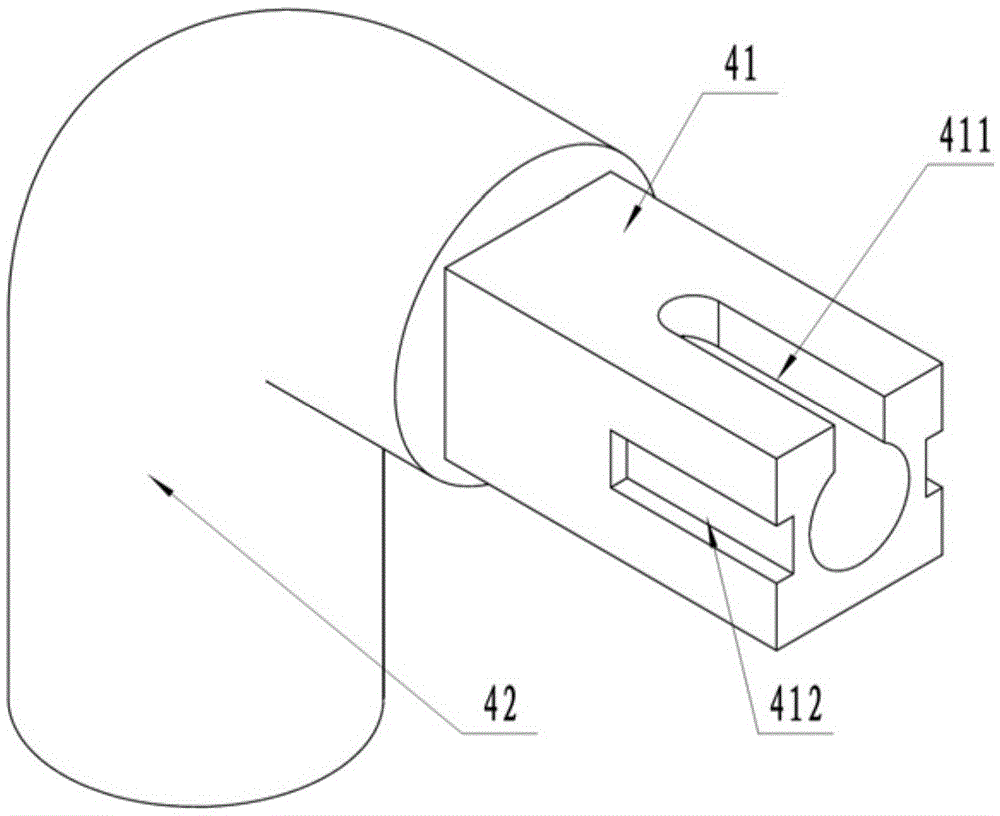
The invention provides an automatic lubrication device arranged between a material barrel and a plunger chip. The automatic lubrication device comprises the material barrel and the inside plunger chip. A plunger rod is connected to one side of the plunger chip, and a channel is formed inside the plunger rod. A right-angled oil guide pipe comprises a butt joint end and a connecting end, wherein the butt joint end is horizontally arranged, and the connecting end is connected with the plunger rod. An oil inlet groove is formed in the top of the butt joint end, and the oil inlet groove, the oil guide pipe and the channel are communicated with one another. An oil storage part is arranged on the material barrel, and the oil guide pipe is located between the plunger chip and the oil storage part. The oil storage part comprises an oil storage chamber, an oil conveying pipe and a butt joint block, wherein the upper end of the oil conveying pipe is communicated with the oil storage chamber, the lower end of the oil conveying pipe is communicated with the butt joint block, a butt joint groove is formed inside the butt joint block, and a piston is arranged inside the butt joint groove. When the return stroke is conducted, the butt joint end and the connecting end enter the butt joint groove, an oil circuit is automatically formed through connection, and a lubricating agent passes through the channel, is perpendicularly sprayed to the inner wall of the material barrel, and then lubricates the plunger chip. When the stroke is conducted, the butt joint end leaves the butt joint groove, the butt joint groove is plugged by the piston, and automatic lubrication of the plunger chip is achieved. The production efficiency is improved, the structure is simple, no electric control systems need to be added, and the cost is low.

Description

technical field [0001] The invention relates to the field of die casting, in particular to an automatic lubricating device between a material cylinder and a punch. Background technique [0002] Die-casting machines are generally divided into two categories: hot-press chamber die-casting machines and cold-press chamber die-casting machines. The pressure chamber of the cold chamber die casting machine is separated from the holding furnace. The liquid metal is easily adsorbed on the inner wall of the pressure chamber, and it is necessary to continuously apply lubricant to the die-casting punch to prevent the die-casting punch from being stuck in the pressure chamber, damage the punch, and affect product quality. At present, the punch oil lubrication method is mostly used between the punch and the pressure chamber. This method is insufficient for lubrication, and die castings are prone to defects. In addition, most punch lubricating devices either cannot automatically lubrica...

Claims


Application Information

Patent Timeline
Patent Type & Authority Applications(China)
IPC IPC(8): B22D17/20
CPCB22D17/2038
Inventor 袁茂凯
Owner 辽宁天海津城装备制造有限公司
Learn More