
Hall pressure sensor

A pressure sensor and mounting part technology, applied in the sensor field, can solve the problems of complex sensor structure and achieve the effect of high-precision pressure sensing

Pending Publication Date: 2019-10-22
江蕾 +1
View PDF0 Cites 2 Cited by
  • Summary
  • Abstract
  • Description
  • Claims
  • Application Information

AI Technical Summary

Problems solved by technology

[0003] Potential sensors are widely used in different fields. For the pressure measurement of liquid fluid or gas fluid, the existing sensor structures are relatively complicated. Therefore, the present invention is dedicated to developing a pressure sensor with a simple structure based on Hall elements sensor

Method used


Image

  • Hall pressure sensor

Examples


Embodiment Construction

[0023] The specific implementation manners of the present invention will be further described in detail below in conjunction with the accompanying drawings and embodiments. The following examples are used to illustrate the present invention, but are not intended to limit the scope of the present invention.

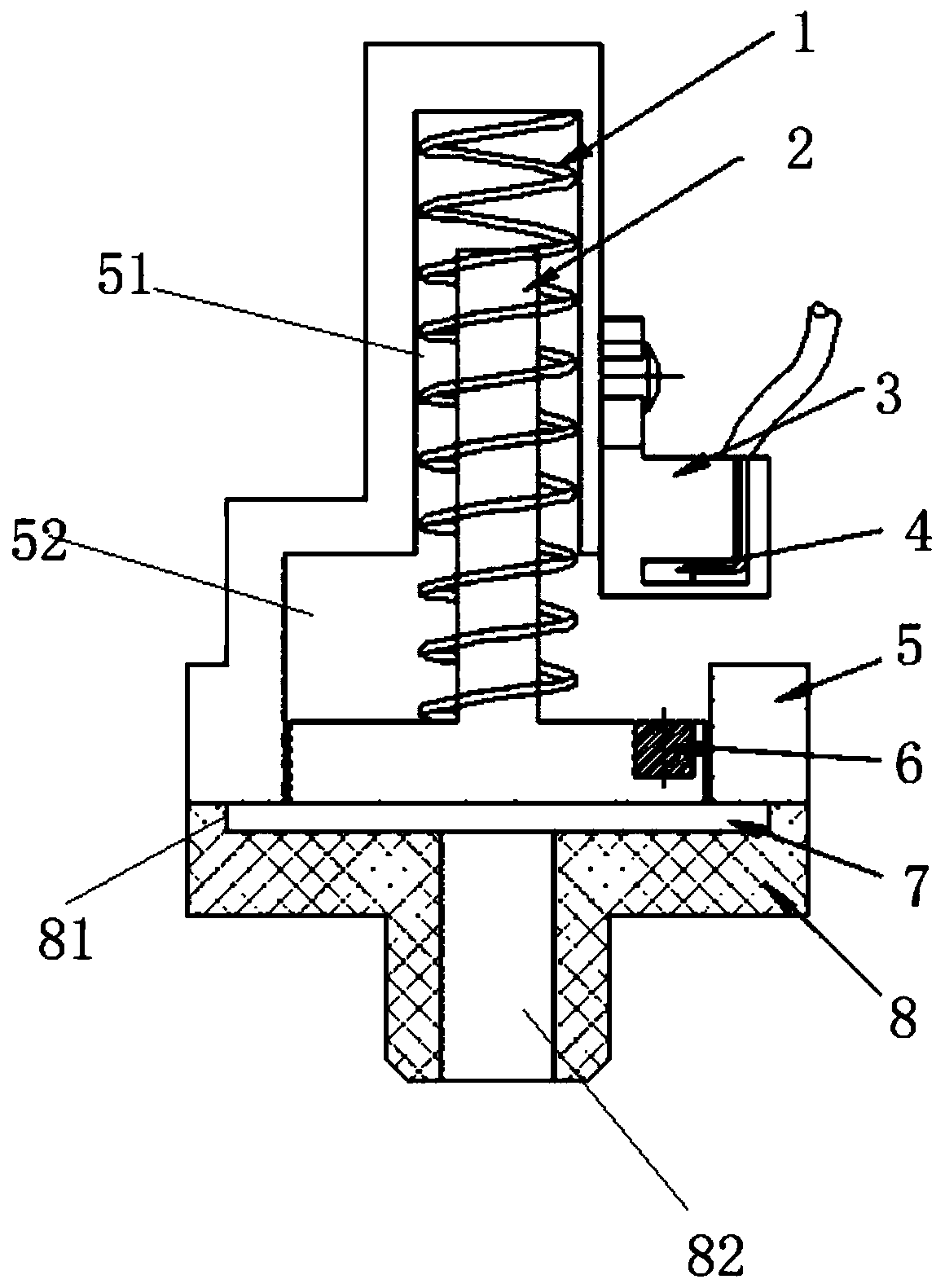
[0024] see figure 1 , a Hall pressure sensor described in a preferred embodiment of the present invention includes a spring seat 5 and a switch seat 8 connected to each other, the switch seat 8 is a flange type, and a cylindrical first installation is arranged on the top of the spring seat 5 Part 51, the bottom of the spring seat 5 is provided with a second mounting portion 52, the diameter of the first mounting portion 51 is smaller than the diameter of the second mounting portion 52; the spring seat 5 and the switch seat 8 are connected by common means when they are specifically connected. It can be glued, screwed, or welded.

[0025] The upper part of the switch base ...


PUM


Abstract

The invention relates to a Hall pressure sensor which comprises a spring seat and a switch seat, wherein the spring seat and the switch seat are connected with each other. A spring and a piston are arranged in the spring seat. The piston comprises a piston disk arranged in a second mounting part, and a piston rod which is connected with the piston disk and extends from the second mounting part into a first mounting part. The spring sleeves the piston rod. One end of the spring abuts against the top of the first mounting part, and the other end of the spring abuts against the piston disk. A leather bag which has the same shape as a third mounting part is arranged in the third mounting part. The piston disk is embedded with a magnet. The spring seat is further provided with an opening abovethe magnet. A Hall element seat is arranged on the side wall of the opening of the spring seat. A Hall element is arranged in the Hall element seat. The device contacts a pressure source through a silica gel sheet, and the elastic property of the silica gel sheet can feed back the pressure of the pressure source well. The silica gel sheet further plays a sealing role.

Description

technical field [0001] The invention relates to a sensor, in particular to a pressure sensor based on a Hall element. Background technique [0002] The Hall sensor is a magnetic field sensor made according to the Hall effect. Hall effect is a kind of magnetoelectric effect. This phenomenon was discovered by Hall (A.H.Hall, 1855-1938) in 1879 when he was studying the conductive mechanism of metals. Later, it was found that semiconductors and conductive fluids also have this effect, and the Hall effect of semiconductors is much stronger than that of metals. Various Hall elements made of this phenomenon are widely used in industrial automation technology, detection technology and information processing, etc. aspect. The Hall effect is a basic method for studying the properties of semiconductor materials. The Hall coefficient measured by the Hall effect experiment can determine important parameters such as the conductivity type, carrier concentration, and carrier mobility of ...

Claims


Application Information

Patent Timeline
IPC IPC(8): G01L1/12G01L9/14
CPCG01L1/127G01L9/14
Inventor 江蕾杨琳江佳航郑智恒
Owner 江蕾
Learn More