

Composite fireproof cable
A fireproof cable and cable technology, applied in the direction of insulated cables, cables, circuits, etc., can solve the problems of poor heat dissipation performance of cables, shorten the service life of cables, prone to spontaneous combustion, etc., and achieve the effect of good heat dissipation performance and increased flame retardant ability.
- Summary
- Abstract
- Description
- Claims
- Application Information
AI Technical Summary
Problems solved by technology
Method used
Image

Examples
Embodiment Construction
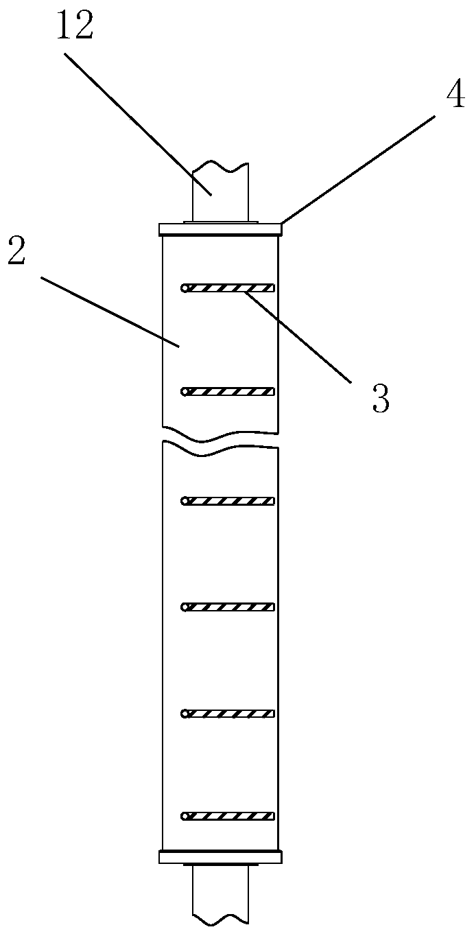
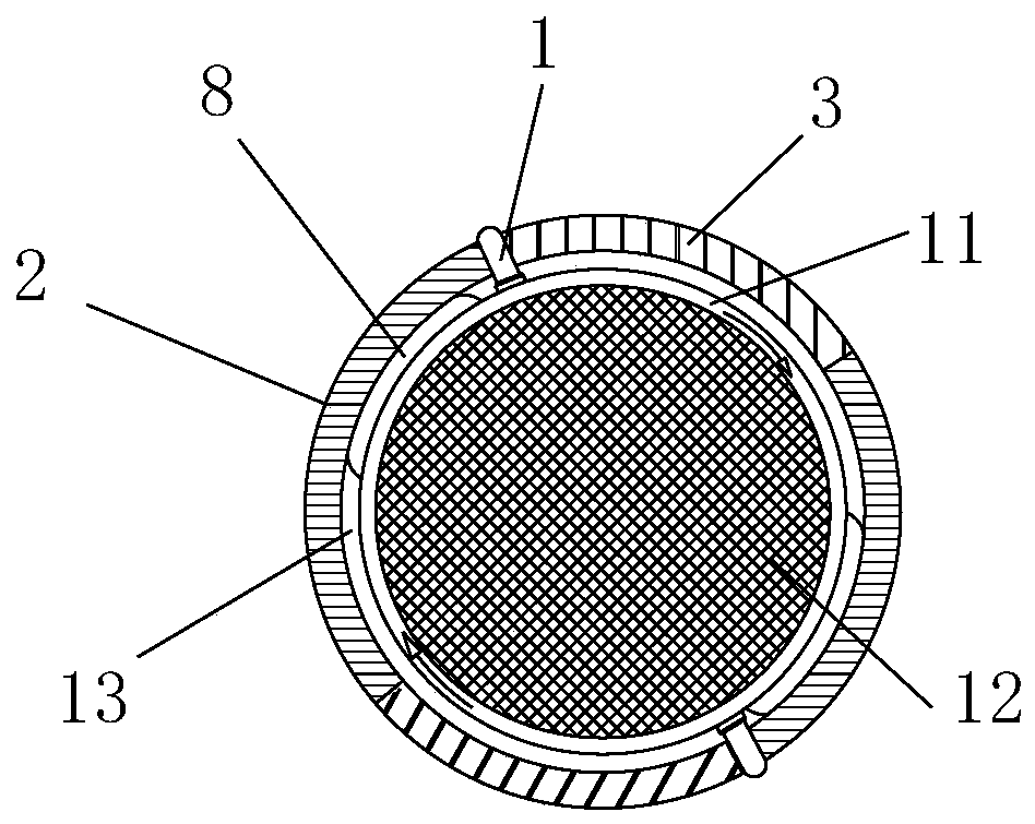
[0018] Such as figure 1 and figure 2 As shown, the composite fireproof cable includes the cable outer protective layer 2, and the cable outer protective layer 2 has a cable installation cavity 13, and the cable main body is installed in the cable installation cavity 13;
[0019] The main body of the cable includes a cable outer layer 11 and a cable core wire 12. An interface 4 is respectively installed at both ends of the cable outer protective layer 2. The cable core wire 12 protrudes outside through the interface 4. The cable core wire 12 and the interface 4 The contact end is fixed with glue;
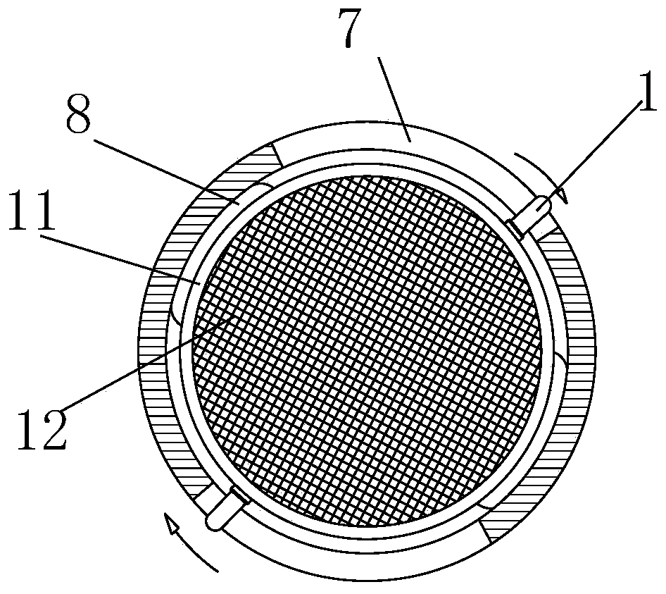
[0020] The two sides of the cable outer layer 11 are respectively symmetrically provided with more than one heat dissipation pin 1, and one end of the heat dissipation pin 1 extends into the arc-shaped groove 7 provided on the cable outer protective layer 2, and the bottom surface of one side of the arc-shaped groove 7 A sealing part 3 is fixedly installed. The inside of the seali...
PUM
 Abstract
Description
Claims
Application Information