Chip heat dissipation packaging structure

A packaging structure and chip heat dissipation technology, applied in electrical components, electrical solid devices, circuits, etc., can solve the problems of insignificant air cooling heat dissipation effect and low heat dissipation efficiency, reduce contact thermal resistance, improve heat dissipation performance, and reduce heat dissipation. good performance

Active Publication Date: 2020-02-11
NAT CENT FOR ADVANCED PACKAGING
View PDF7 Cites 4 Cited by
  • Summary
  • Abstract
  • Description
  • Claims
  • Application Information

AI Technical Summary

Problems solved by technology

[0005] Therefore, the technical problem to be solved by the present invention is to overcome the inconspicuous heat dissipation effect and l

Method used


Image

  • Chip heat dissipation packaging structure

Examples


Example Embodiment

[0035] Example 1

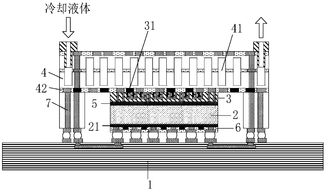
[0036] Such as figure 1 As shown, this embodiment relates to a chip heat dissipation package structure, which includes a substrate 1, a semiconductor refrigeration chip 3, and a micro-channel chip 4.

[0037] The working chip 2 is mounted on the substrate 1. The working chip 2 is the chip to be dissipated. The semiconductor cooling chip 3 is mounted on the working chip 2, and the semiconductor cooling chip 3 is located on the working chip 2 on the side opposite to the substrate 1. The cooling chip 3 is used to dissipate heat from the working chip 2. The micro-channel chip 4 is mounted on the semiconductor refrigeration chip 3, the micro-channel chip 4 is located on the side of the semiconductor refrigeration chip 3 opposite to the working chip 2, and the micro-channel chip 4 is used to dissipate the semiconductor refrigeration chip 3.

[0038] Among them, in order to enhance the heat dissipation effect of the semiconductor refrigeration chip 3 and the micro-chann...


PUM


Abstract

The invention relates to the field of chip packaging, in particular to a chip heat dissipation packaging structure, which comprises a substrate loaded with a working chip, a semiconductor refrigeration chip arranged on the working chip for cooling the working chip, and a micro-channel chip arranged on the semiconductor refrigeration chip for cooling the semiconductor refrigeration chip. The semiconductor refrigeration chip is arranged on the working chip, and thus, heat dissipated by the working chip can be directly and actively dissipated; the semiconductor refrigeration chip is provided withthe micro-channel chip, and the micro-channel chip is used for dissipating heat of the semiconductor refrigeration chip, so that the heat dissipation efficiency of the working chip is higher, and theheat dissipation effect is obvious; and as a thermoelectric conversion layer is also arranged between the working chip and the substrate and is used for converting heat of the working chip into electric energy and driving the semiconductor refrigeration chip or the micro-channel chip to work, an external power supply is prevented from being arranged, and energy is saved.

Description

technical field [0001] The invention relates to the field of chip packaging, in particular to a chip heat dissipation packaging structure. Background technique [0002] With the continuous improvement of the integration and function of electronic devices, the heat flux density of some devices in electronic products and electronic equipment also increases, which puts forward higher and higher requirements for heat dissipation technology. [0003] At present, the most widely used heat dissipation technology is air cooling technology. Air cooling refers to a heat dissipation method that takes away the heat generated by electronic components through the flow of air, including natural convection and forced convection. The natural convection air cooling technology mainly uses the gaps of various components in the equipment and the heat conduction, convection and radiation of the casing to achieve the purpose of cooling and heat dissipation. Natural convection is often used to coo...

Claims


Application Information

Patent Timeline
IPC IPC(8): H01L23/38H01L23/473H01L23/367H01L23/373
CPCH01L23/3677H01L23/373H01L23/38H01L23/473H01L2224/16225H01L2224/73253H01L2924/15192
Inventor 曹立强徐成孙鹏
Owner NAT CENT FOR ADVANCED PACKAGING
Why Eureka
Try Eureka