
COB light source and manufacturing method thereof

A light source and light distribution technology, applied in semiconductor devices, electrical components, circuits, etc., can solve problems such as affecting light extraction efficiency, adverse production costs, and inability to focus, and achieve the effect of ensuring light extraction efficiency

Inactive Publication Date: 2019-10-22
FOSHAN EVERCORE OPTOELECTRONICS TECH
View PDF3 Cites 1 Cited by
  • Summary
  • Abstract
  • Description
  • Claims
  • Application Information

AI Technical Summary

Problems solved by technology

[0002] COB light sources are mainly used in lighting places with high brightness requirements. Existing lighting places with high brightness requirements usually need to install multiple COB light sources to meet their brightness requirements. This method is costly and causes a lot of energy waste. , so improving the light extraction efficiency of the COB light source is an urgent problem to be solved
[0003] Based on this, someone proposed to install a lens on the COB light source to achieve light concentration and improve the light output efficiency of the COB light source. Although this method increases the light output efficiency to a certain extent, because the light emitted by the COB light source needs to pass through once Colloid, air and lens, the refractive index of colloid and lens is 1.5, the refractive index of air is 1, the refractive index changes stepwise, and the surface of the colloid is flat, resulting in total reflection of part of the light and cannot be fully emitted; secondly, usually The light emitting surface of the COB light source is relatively large, requiring the use of bulky lenses. The production cost of the lens is high, which is not conducive to saving production costs; finally, the light emitting surface of the COB light source is a surface, which cannot be focused, so that the respective functions cannot be fully utilized. Maximum, affecting its light extraction efficiency

Method used


Image

  • COB light source and manufacturing method thereof
  • COB light source and manufacturing method thereof
  • COB light source and manufacturing method thereof

Examples


Embodiment approach 1

[0060] Implementation mode one: if Figure 4-5 As shown, the LED chips 3 of each group are distributed in a strip shape, and the LED chips 3 of each group are parallel to each other; Parallel; the light distribution element 51 is strip-shaped, and there are multiple pieces. One light distribution element 51 covers a group of LED chips 3 to complete the light distribution of the group of LED chips 3 .

[0061] The light distribution part 5 has an axisymmetric structure. Preferably, the cross section of the light distribution part 5 is semicircular, and the LED chip 3 is located on the center of the semicircle to realize light distribution and ensure COB The light source achieves the best light extraction efficiency.

[0062] It should be noted here that, in this embodiment, the cross section of the light distribution member 51 is a plane perpendicular to the upper surface of the substrate 1 and the longitudinal direction of the light distribution member 51 .

[0063] In order...

Embodiment approach 2

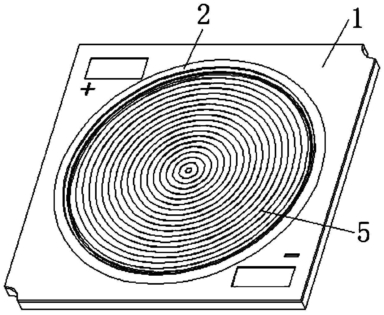
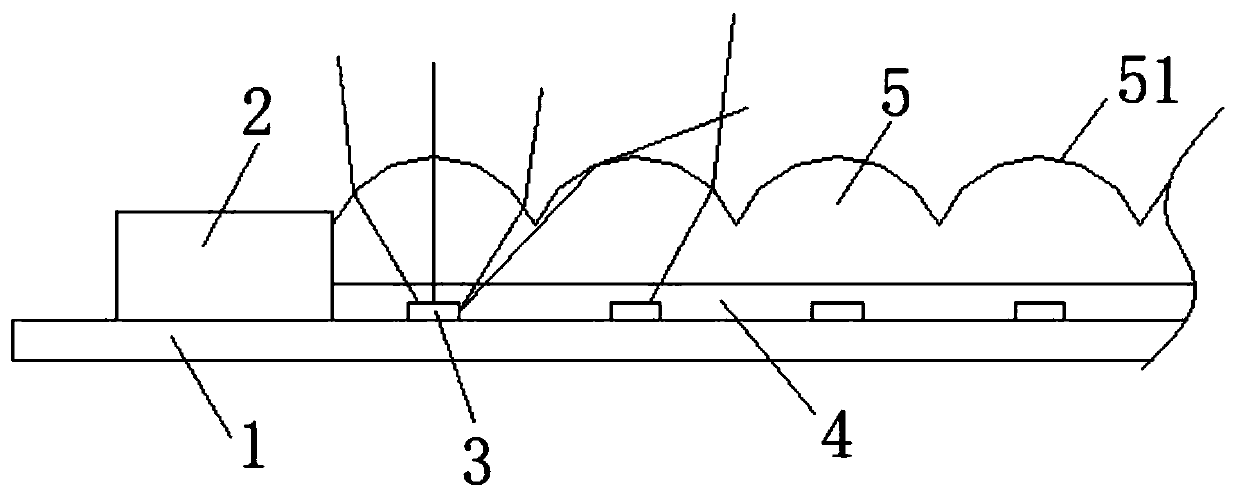
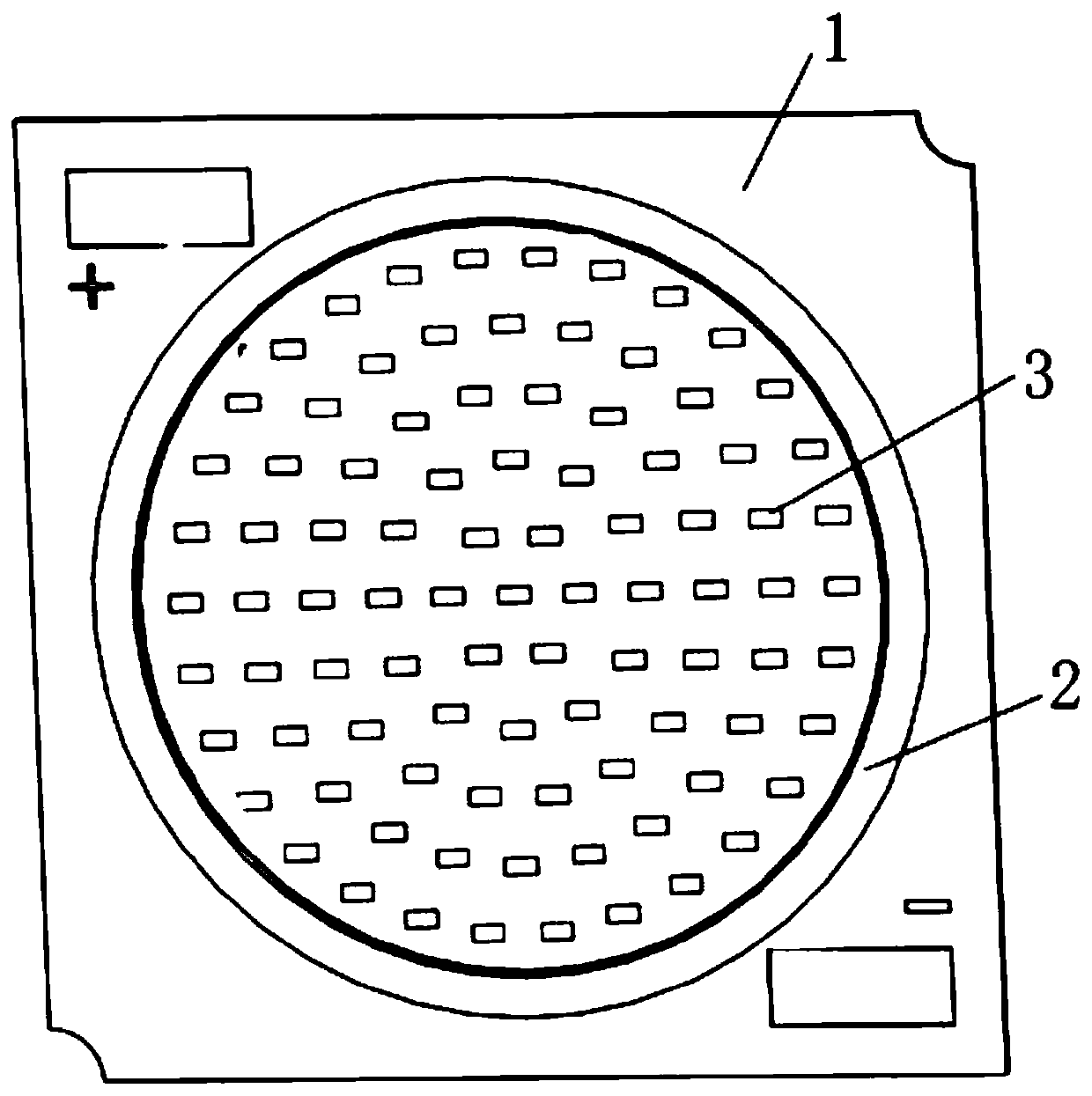
[0065] Implementation mode two: if Figure 1-3 As shown, the LED chips 3 in each group are distributed in a ring shape, and the LED chips 3 in each group are distributed in concentric circles; the dam 2 is in a ring shape, and the dam 2 and each group of LED chips 3 are concentric circles; The light distribution member 51 is ring-shaped, and there are multiple ones. One light distribution member 51 covers a group of LED chips 3 to complete the light distribution of the group of LED chips.

[0066] The cross section of the light distribution element 51 is axisymmetric. Preferably, the cross section of the light distribution element 51 is semicircular, and the LED chip 3 is located on the center of the semicircle to realize light distribution. , to ensure that the COB light source achieves the best light extraction efficiency.

[0067] It should be noted here that, in this embodiment, the cross-section of the light distribution element is a straight line that is perpendicular t...

other Embodiment approach

[0077] In other embodiments, the injection-molded light distribution layer can also be adhered to the surface of each group of LED chips to realize the light distribution effect, wherein the light distribution layer is made of silica gel, PC or PMMA material, which depends on the actual LED The layout structure of the chip is provided with several light distribution parts matching with the LED chip.

[0078] The LED chip 3 is located on the symmetrical axis of the cross-section of the light distribution member 51 matched therewith;

[0079] The maximum width of the light distribution element 51 is 1.5-10 times the length of the LED chip 3;

[0080] On the cross section of the light distribution member 51 , the distance between the light emitting surface of the light distribution member 51 and the LED chip 3 is 1-10 times the height of the LED chip 3 .

[0081] In order to ensure the light extraction efficiency of the COB light source, the shape of the light distribution membe...


PUM


Abstract

The invention relates to a COB light source. The COB light source comprises a substrate, a dam positioned on the substrate, an LED chip positioned in the dam, a packaging adhesive layer covering the LED chip and a light distribution layer covering the packaging adhesive layer. The light distribution layer comprises a plurality of light distribution pieces, the light emitting surfaces of the lightdistribution pieces are arc-shaped, and the cross sections of the light distribution pieces are in an axisymmetric structure. Correspondingly, the invention also provides a manufacturing method of theCOB light source. According to the COB light source, the packaging adhesive layer is directly covered with the light distribution layer, the refractive indexes of the light distribution layer and thepackaging adhesive layer are not greatly different, light emitted by the LED chip is directly emitted through the packaging adhesive layer and the light distribution layer, the step-shaped refractiveindex change is avoided, and light rays can be emitted; and moreover,, the light emitting surfaces of the light distribution pieces is arc-shaped, so that the light rays of the COB light source are emitted in a concentrated manner and are not scattered to a peripheral area, and the light emitting efficiency of the COB light source is further ensured.

Description

technical field [0001] The present invention relates to the technical field of LED lighting equipment, in particular to a COB light source and a manufacturing method thereof. Background technique [0002] COB light sources are mainly used in lighting places with high brightness requirements. Existing lighting places with high brightness requirements usually need to install multiple COB light sources to meet their brightness requirements. This method is costly and causes a lot of energy waste. , so improving the light extraction efficiency of the COB light source is an urgent problem to be solved. [0003] Based on this, someone proposed to install a lens on the COB light source to achieve light concentration and improve the light output efficiency of the COB light source. Although this method increases the light output efficiency to a certain extent, because the light emitted by the COB light source needs to pass through once Colloid, air and lens, the refractive index of c...

Claims


Application Information

Patent Timeline
Patent Type & Authority Applications(China)
IPC IPC(8): H01L33/58H01L25/075
CPCH01L33/58H01L25/0753H01L2933/0058
Inventor 王孟源曾伟强董挺波
Owner FOSHAN EVERCORE OPTOELECTRONICS TECH
Learn More