Direct-drive hub motor of wheelchair

A hub motor and wheelchair vehicle technology, applied in the direction of electric components, electrical components, electromechanical devices, etc., can solve the problems of not having modern vehicle aesthetics, the influence of rotation balance, and occupying the space of the vehicle, so as to achieve large braking force and overall Optimized car structure and short braking time

Pending Publication Date: 2019-10-22
NANJING KANGNI SMART TECH CO LTD
View PDF0 Cites 3 Cited by
  • Summary
  • Abstract
  • Description
  • Claims
  • Application Information

AI Technical Summary

Problems solved by technology

[0002] Most of the drive motors used in existing wheelchairs are brushless or brushless toothed hub motors with complex internal structures. The rotor assembly is formed by mechanical connections of multiple parts. The braking part is completed relying on the external mechanical brake structure, such as disc brakes, servo brakes, drum brakes, etc., with brake lines and manual brake handles to achieve vehicle braking
This type of braking method has a long transmission line and a relatively complicated structure. In addition, the brake parts are exposed, and dus

Method used


Image

  • Direct-drive hub motor of wheelchair
  • Direct-drive hub motor of wheelchair
  • Direct-drive hub motor of wheelchair

Examples


Embodiment 1

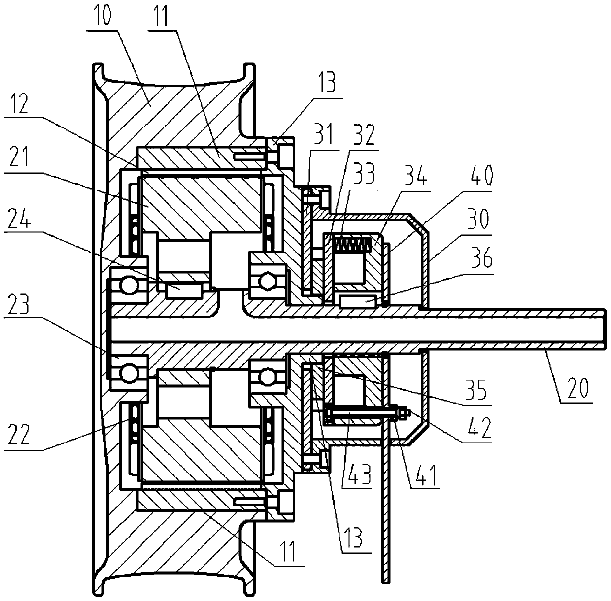
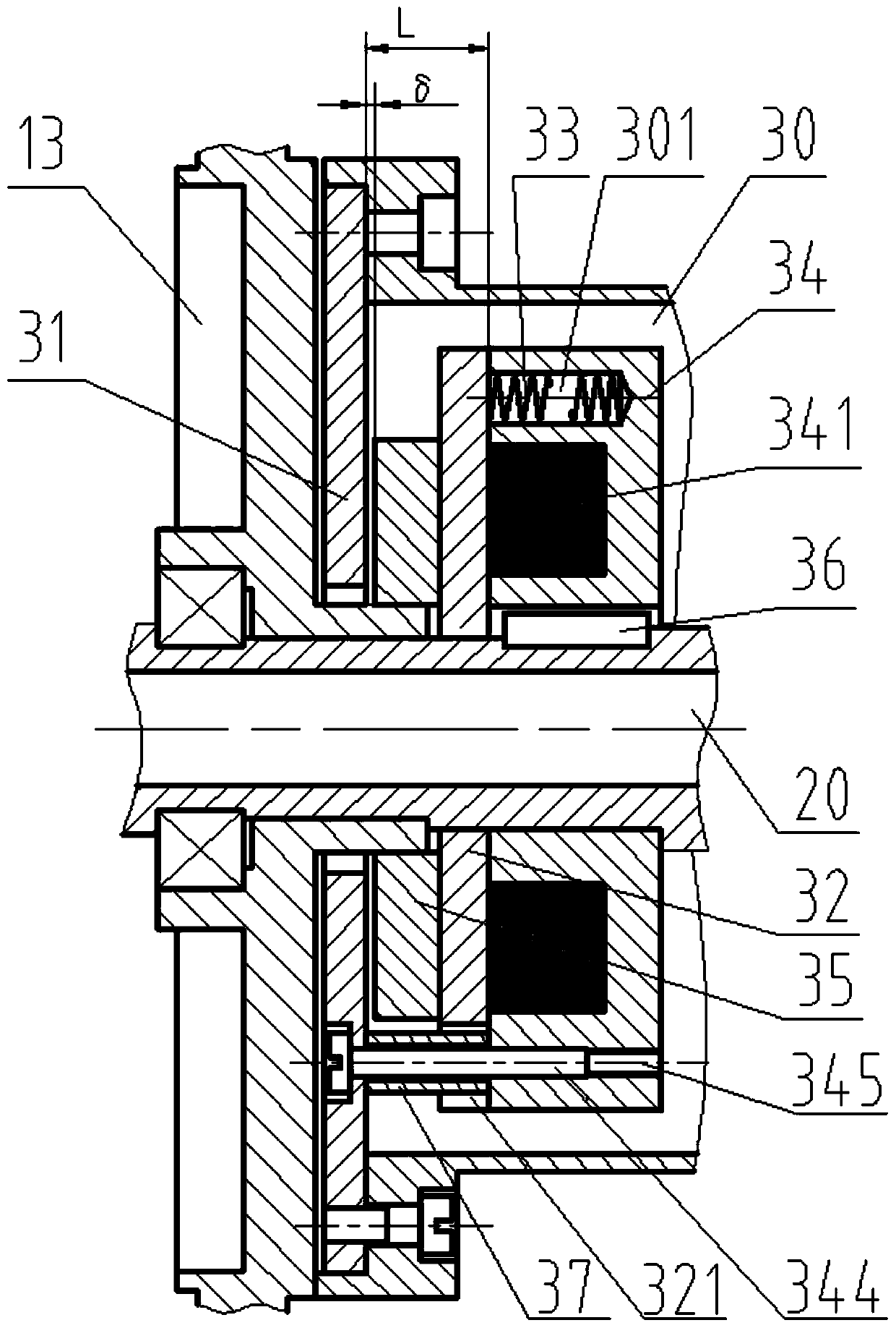
[0039] Such as figure 1 , the motor of this embodiment is mainly composed of a hub 10, a rotor core 11, a magnetic steel 12, a support seat 13, a stator 21, a winding 22, a motor shaft 20, a stator 31, a moving plate 32, a friction plate 35, a spring 33, a magnetic Brake seat 34, unlocking handle 40 and transmission rod 43 form.

[0040] The stator 21 is connected on the motor shaft 20, and is non-rotatably connected with the motor shaft through the key 24, and the winding 22 is arranged at both axial ends of the stator, thus the stator 21, the winding 22 and the motor shaft 20 constitute a stator assembly.

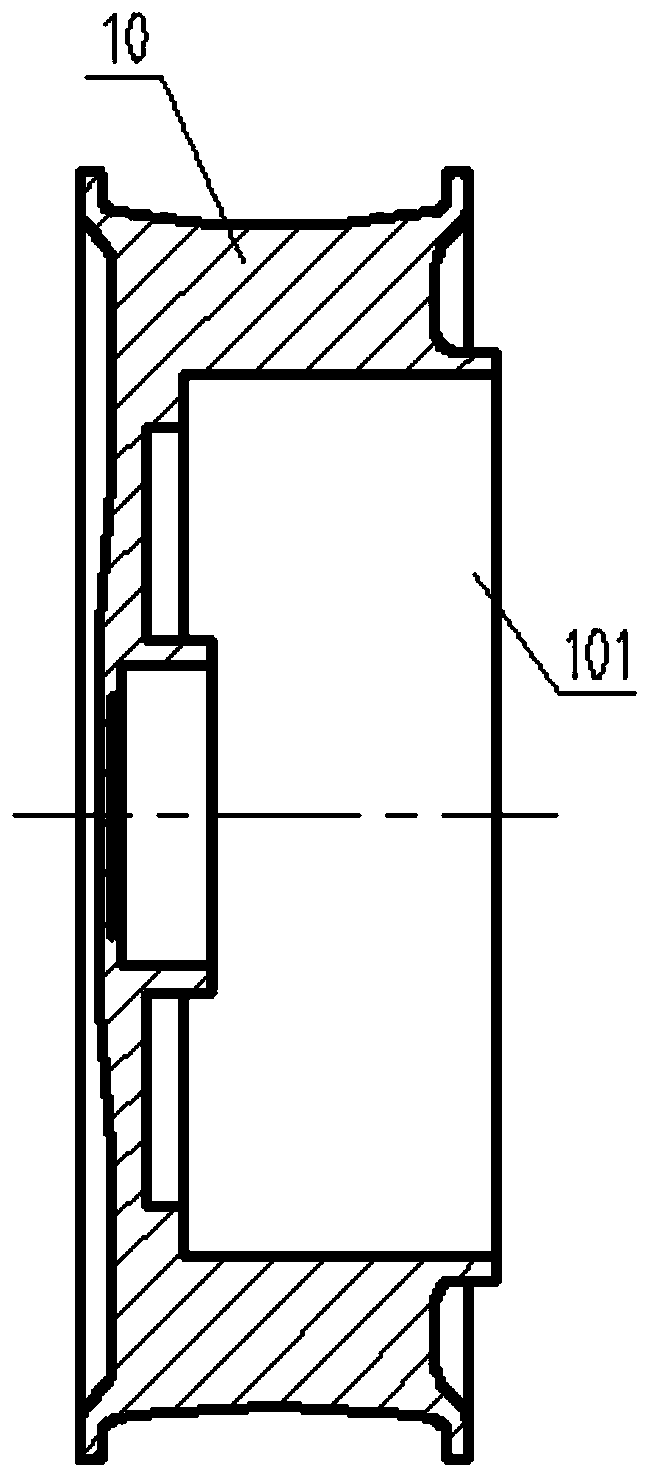
[0041] Such as figure 2 , the axial end of the hub 10 is provided with a rotor groove 101, the rotor core 11 and the magnetic steel 12 are both annular, and the rotor core is fixed on the annular wall surface of the rotor groove of the hub by casting , the magnetic steel is fixedly connected to the inner circular surface of the rotor iron core, thus the hub 1, the roto...

Embodiment 2

[0049] The motor of this embodiment is as Figure 14 As shown, the difference from the above-mentioned embodiment 1 is that the structures of the hub and the rotor core are slightly different, such as Figure 15 , 16 A protruding ring 102 is provided on the circular wall surface of the rotor groove 101 on the hub 10, and an annular groove 111 matching the protruding ring 102 is provided on the circumferential side of the rotor core 11. The rotor groove 101 on the hub is actually produced during casting. The hub and the rotor core are mutually axially limited by the cooperation of the protruding ring 102 and the annular groove 111. Even if the casting joint surfaces of the two are separated due to long-term vibration, the rotor core will not move axially. Therefore, the structure in which the hub and the rotor core are combined with each other in this embodiment makes the rotor assembly have the fewest connecting parts, and the whole is good, so the rotation balance is good. ...


PUM


Abstract

The invention relates to a direct-drive hub motor of a wheelchair. The direct-drive hub motor of the wheelchair comprises a hub, a rotor core, magnetic steel, a supporting seat, a stator, a motor shaft, a stator plate, a rotor plate, a friction plate, a spring, an unlocking handle, a transmission rod and a magnetic brake seat. The stator is connected with the motor shaft to form a stator component; a rotor component consisting of the hub, the rotor core, the magnetic steel and a supporting seat wheel is rotatably supported on the motor shaft, wherein the rotor core is fixedly connected in therotor groove; the stator plate is connected with the magnetic brake seat with an interval L, the friction plate and the rotor plate are axially and movably arranged in the interval, the sum of the thicknesses of the friction plate and the rotor plate is smaller than L, and the spring is arranged between the rotor plate and the magnetic brake seat; the unlocking handle sleeves the motor shaft and is circumferentially distributed with a plurality of lugs, the lugs are provided with arc slotted holes, the upper ends of the arc slotted holes are provided with spiral surfaces, the transmission rodpenetrates the arc slotted holes and one end of the magnetic brake seat to be connected with the rotor plate, and one end of the transmission rod is connected with the unlocking handle. The direct-drive hub motor of a wheelchair has good dynamic balance and braking response, and the brake state can be manually released in a power-off state.

Description

technical field [0001] The invention relates to a direct drive internal brake motor of a wheelchair. Background technique [0002] Most of the drive motors used in existing wheelchairs are brushless or brushless toothed hub motors with complex internal structures. The rotor assembly is formed by mechanical connections of multiple parts. The braking part of the vehicle is completed relying on the external mechanical brake structure, such as disc brakes, servo brakes, drum brakes, etc., with brake lines and manual brake handles to achieve vehicle braking. This type of braking method has a long transmission line and a relatively complicated structure. In addition, the brake parts are exposed, and dust and sand enter the period, causing the corresponding brake components to wear and weaken the braking effect; at the same time, some operations of the operating parts will produce some unnecessary Even unsafe actions, such as manual brake levers, the wheels will rotate freely when...

Claims


Application Information

Patent Timeline
IPC IPC(8): H02K1/27H02K7/00H02K7/102H02K5/16
CPCH02K1/2786H02K5/165H02K7/003H02K7/1021
Inventor 张墨染唐达联柯旭
Owner NANJING KANGNI SMART TECH CO LTD
Why Eureka
Try Eureka