
A FM demodulation device based on fiber grating sensor array

A technology of sensor array and fiber grating, applied in the field of optical communication

Active Publication Date: 2020-10-20
ZHEJIANG UNIV
View PDF10 Cites 0 Cited by
  • Summary
  • Abstract
  • Description
  • Claims
  • Application Information

AI Technical Summary

Problems solved by technology

[0004] However, the above scheme is only designed for a single hydroacoustic sensor. In practical applications, optical fiber sensors are usually arranged in the form of sensor arrays to achieve multiplexing. Therefore, it is necessary to redesign an optical fiber sensor sensing array implemented by single sideband frequency modulation. and its demodulation system

Method used


Image

  • A FM demodulation device based on fiber grating sensor array
  • A FM demodulation device based on fiber grating sensor array
  • A FM demodulation device based on fiber grating sensor array

Examples


Embodiment Construction

[0034] In order to describe the present invention more specifically, the technical solutions of the present invention will be described in detail below in conjunction with the accompanying drawings and specific embodiments.

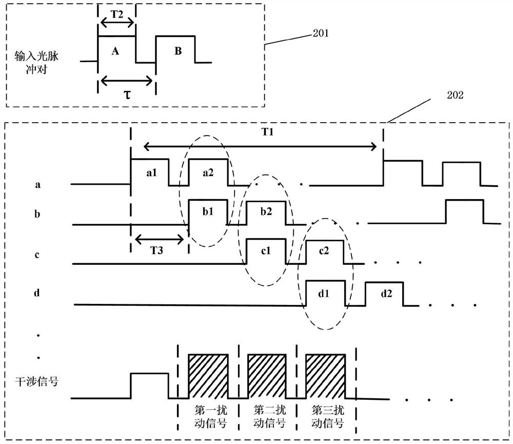
[0035] Such as figure 1As shown, the present invention is based on the FM demodulation device of the fiber grating sensor array, including a laser 101, an acousto-optic modulator 102, a delay fiber pair 116, a Mach-Zehnder modulator 107, an optical bandpass filter 108, and an optical amplifier connected in sequence 110, optical isolator 111, circulator 112, fiber grating sensor array 113, photodetector 114, data sampling card 115 and radio frequency signal source 109; Wherein:

[0036] The narrow-linewidth light source 101 generates a continuous narrow-linewidth optical signal and transmits it to the acousto-optic modulator 102, and the acousto-optic modulator 102 is a frequency shifter to shift the frequency of the light source by f (f=2π / ω 1 ), it is a...


PUM


Abstract

The invention discloses a frequency modulation demodulation device based on a fiber grating sensor array, including a laser, a radio frequency signal source, an acousto-optic modulator, a delay fiber pair, a Mach-Zehnder modulator, an optical filter, an optical amplifier, an optical isolator, Circulators, fiber grating sensor arrays, photodetectors, and data sampling cards. In the present invention, by delaying the combined use of the optical fiber pair and the optical fiber grating, the reflected light pulses of the front and rear two gratings overlap in the time domain to form interference, and realize multi-point array interference demodulation. The device of the invention has the advantages of simple structure, easy realization of demodulation algorithm, high demodulation precision, simple realization and the like.

Description

technical field [0001] The invention belongs to the technical field of optical communication, and in particular relates to a frequency modulation and demodulation device based on a fiber grating sensor array. Background technique [0002] Acoustic waves are the only form of energy that can travel long distances in the ocean, and hydrophones are the basic devices for detecting acoustic signals in the ocean; fiber optic sensors are used as hydrophones, which have high sensitivity, strong anti-electromagnetic interference, and resistance to harsh underwater conditions. environment and other characteristics. With the development of marine science, large-scale and miniaturization have become an important direction for the development of fiber optic hydrophone arrays; however, with the deepening of applications, traditional fiber optic hydrophone arrays have shown their limitations, which are mainly reflected in Traditional hydrophone arrays have complex structures, small detecta...

Claims


Application Information

Patent Timeline
Patent Type & Authority Patents(China)
IPC IPC(8): H04B10/54H04B10/516H04B10/508H04B10/50
CPCH04B10/503H04B10/508H04B10/516H04B10/54G01D5/35316G01D5/35393G01H9/004G02B6/29352G01D5/35383
Inventor 金晓峰程志威欧坚海金向东杜一杰谢银芳
Owner ZHEJIANG UNIV
Learn More