Optical transmitter, wavelength alignment method and passive optical network system
An optical transmitter and a technology of emitting light, which is applied in the field of optical fiber communication, can solve the problems that DML cannot adapt to the transmitter, and the chirp phenomenon is serious.
- Summary
- Abstract
- Description
- Claims
- Application Information
AI Technical Summary
Problems solved by technology
Method used
Image
Examples
Embodiment 1
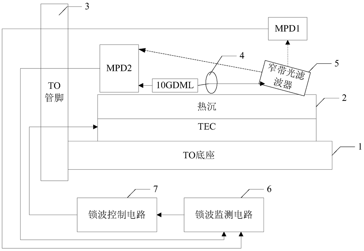
[0119] Such as figure 1 As shown, it is an optical transmitter disclosed in the embodiment of the present invention, which mainly includes:
[0120] TO base 1, TEC and heat sink 2 connected horizontally from bottom to top;
[0121] a TO pin 3 connected to one end of the TO base 1 on one side;
[0122] The second MPD ( figure 1 shown as MPD2), 10GDML, collimator lens 4 and narrow-band optical filter 5, wherein, the MPD2 and the collimator lens 4 are located on both sides of the 10GDML, and the narrow-band optical filter 5 is located on the collimator The other side of the collimating lens 4, and the side facing the collimating lens 4 is connected to the heat sink 2 at a preset inclination angle;
[0123] The first MPD ( figure 1 shown as MPD1 in );
[0124] A wave-locking monitoring circuit 6 connected to the TO pin 3 arranged on one side of the TO base 1, and a wave-locking control circuit 7 connected to the wave-locking monitoring circuit 6;
[0125] Wherein, the forward ...
Embodiment 2
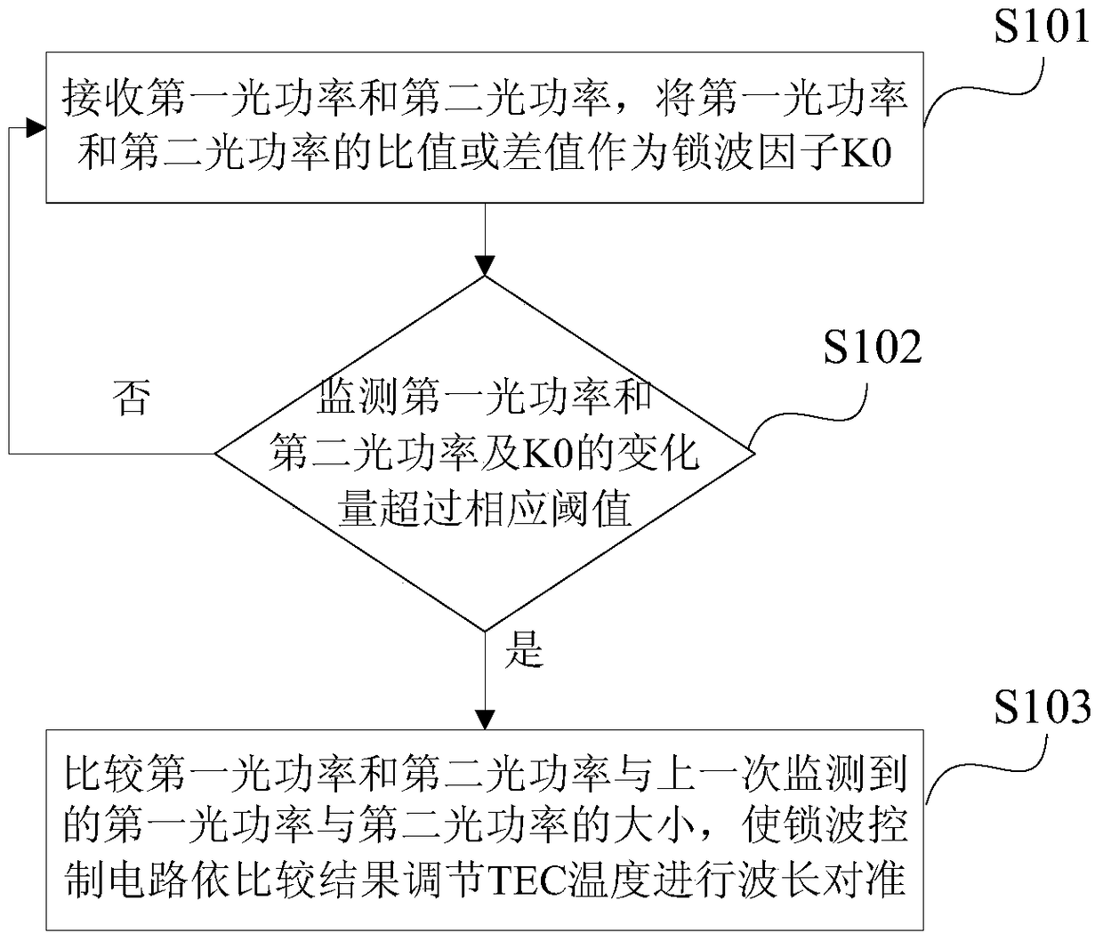
[0139] On the basis of the optical transmitter disclosed in the first embodiment of the present invention, based on the optical transmitter, the embodiment of the present invention also discloses a wavelength alignment method correspondingly. The method is based on the aforementioned figure 1 The structure diagram of the optical transmitter shown in figure 2 As shown, it mainly includes the following steps:
[0140] Step S101, the wave-locking monitoring circuit receives the first optical power of the forward transmitted light monitored by the first MPD through the TO pin and the second optical power of the complementary backward emitted light and retroreflected light monitored by the second MPD, and the The ratio or difference between the first optical power and the second optical power is used as the wave locking factor K0;
[0141] During the execution of step S101, based on the attached figure 1 In the disclosed optical transmitter, the forward transmitted light monitor...
Embodiment 3
[0150]On the basis of the optical transmitter disclosed in the first embodiment of the present invention and the wavelength alignment method disclosed in the second embodiment of the present invention, in step S101, the wave-locking monitoring circuit receives the first MPD through the TO pin to monitor the forward transmitted light Before the second optical power of the first optical power and the second MPD monitoring the second optical power after the back-emitted light and the back-reflected light are complementary, the following steps are also included:
[0151] In step S100, the wave-locking monitoring circuit reads the TEC temperature at the standard operating point, the first standard optical power M1 of the first MPD, and the second standard optical power M2 of the second MPD, and in the preset wavelength effective region with t* M1+M2 calculates the average optical power Pa, and uses Pa as the input of the automatic optical power control loop, wherein the input end of...
PUM
 Abstract
Description
Claims
Application Information
 - R&D
- Intellectual Property
- Life Sciences
- Materials
- Tech Scout
- Unparalleled Data Quality
- Higher Quality Content
- 60% Fewer Hallucinations
Browse by: Latest US Patents, China's latest patents, Technical Efficacy Thesaurus, Application Domain, Technology Topic, Popular Technical Reports.
© 2025 PatSnap. All rights reserved.Legal|Privacy policy|Modern Slavery Act Transparency Statement|Sitemap|About US| Contact US: help@patsnap.com


