Workpiece production line, workpiece cleaning machine and workpiece cleaning groove

A cleaning tank and cleaning machine technology, which is applied to metal processing machinery parts, manufacturing tools, metal processing equipment, etc., can solve the problems of high water change frequency, unclean workpiece cleaning, low cleaning efficiency, etc., and achieve low water change frequency, Avoid secondary attachment and clean the effect

Pending Publication Date: 2019-10-25
SUZHOU INST OF INDAL TECH
View PDF8 Cites 1 Cited by
  • Summary
  • Abstract
  • Description
  • Claims
  • Application Information

AI Technical Summary

Problems solved by technology

[0004] In the prior art, the water in the water tank is mixed with a large amount of cleaned chips, which makes the chips adhere to the surface of the workpiece for the second time. There is a problem that the workpiece is not cleaned cleanly, and the frequency of water change is also high, resulting in low cleaning efficiency.

Method used


Image

  • Workpiece production line, workpiece cleaning machine and workpiece cleaning groove
  • Workpiece production line, workpiece cleaning machine and workpiece cleaning groove
  • Workpiece production line, workpiece cleaning machine and workpiece cleaning groove

Examples


Embodiment 1

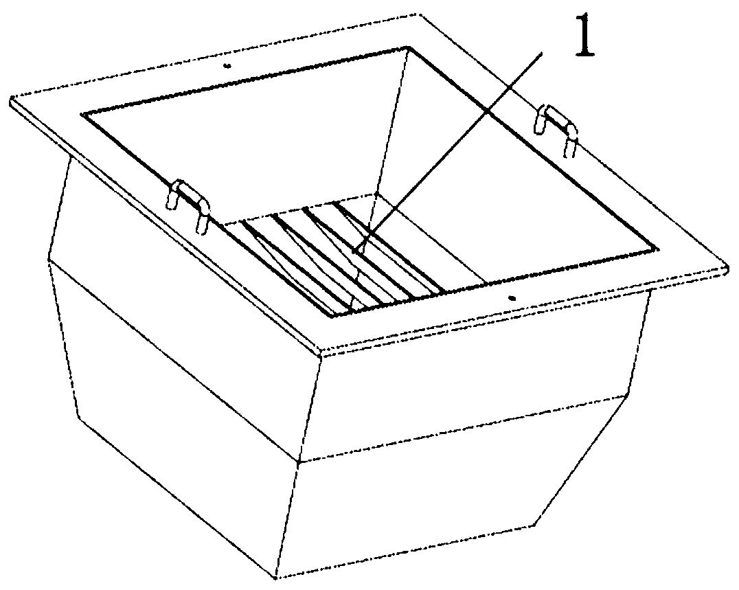
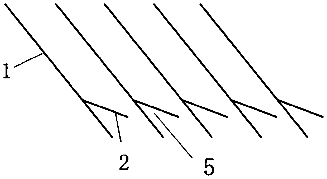
[0028] see figure 1 , figure 2 , image 3 , this embodiment provides a workpiece cleaning tank 3, a plurality of chip guide plates 1 arranged in the same direction are arranged between the first tank wall and the second tank wall opposite to the workpiece cleaning tank 3, and the chip guide plates 1 There is a certain distance between them, the chip guide plate 1 is arranged obliquely, the inclination direction of the chip guide plate 1 can be the same or different, preferably the same, the horizontal distance between the upper ends of the chip guide plate 1 is smaller than the size of the workpiece, so that the workpiece Will not fall, swarf can fall. The upper space of the chip guide plate 1 is a workpiece cleaning area, and the lower space of the chip guide plate 1 is a chip storage area. The chip storage area is used to store chips that slide down through the plurality of chip guide plates 1, and the chips are removed from the workpiece. The surface falls into the chip...

Embodiment 2

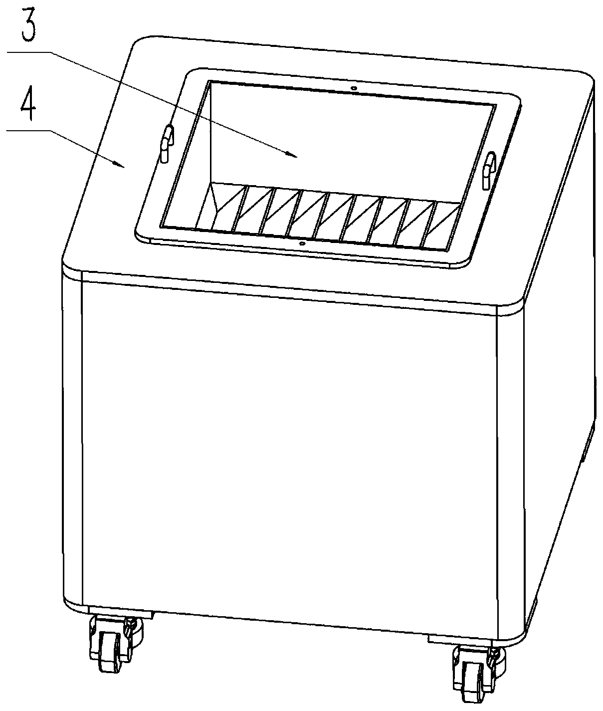
[0033] The present invention also provides a workpiece cleaning machine 4, which includes the workpiece cleaning tank 3 in Embodiment 1. The workpiece cleaning machine 4 can also be equipped with a water pump instead of manually changing the water. An angle is set between the chip barrier 2 in the workpiece cleaning tank 3 and the upper surface of the chip guide 1, that is to say, a chip blocking space 5 is provided between the chip barrier 2 and the chip guide 1, The chip barrier 2 can be a straight plate obliquely downward, or a downward curved arc plate. There is a small gap between the second end of the chip barrier 2 and the adjacent chip guide plate 1, which can make the chips Through this, a channel with a large top and a small bottom is formed so that the chips can fall, but they cannot move upward again into the cleaning area. The cleaning machine is clean and the water change frequency is low.

Embodiment 3

[0035] The present invention also provides a workpiece production line, including the workpiece cleaning tank 3 in Embodiment 1 or the workpiece cleaning machine 4 in Embodiment 2. The workpiece cleaning tank 3 in the production line can isolate the cleaned chips, avoid the secondary attachment of the chips, and improve the overall production efficiency and yield.


PUM


Abstract

The invention discloses a workpiece cleaning groove. A plurality of chip guide plates are arranged between opposite first groove wall and second groove wall of the workpiece cleaning groove; the chipguide plates are arranged slantwise; the upper space of each chip guide plate is a workpiece cleaning area; the lower space of each chip guide plate is a chip storage area; and each chip storage areais used for storing chips sliding off via the plurality of chip guide plates. The chip guide plates arranged slantwise are capable of effectively preventing the chips from continuing to move upwards,secondary attachment of the chips is avoided, and the water change frequency is reduced, so that thorough cleaning, high efficiency and low cost are achieved. The invention further discloses a workpiece cleaning machine. The workpiece cleaning machine comprises the workpiece cleaning groove. The invention further discloses a workpiece production line. The workpiece production line comprises the workpiece cleaning groove or the workpiece cleaning machine.

Description

technical field [0001] The invention belongs to the field of workpiece cleaning in industrial production, and in particular relates to a workpiece production line, a workpiece cleaning machine and a workpiece cleaning tank. Background technique [0002] Metal cutting is a commonly used processing method in today's machinery manufacturing. It uses cutting tools to remove excess metal from the blank. Metal workpieces processed on machine tools often leave a part of chips and cutting fluid. When changing the clamping surface or entering the lower In one process, it is necessary to ensure that there are no chips on the clamping surface, otherwise it will affect the machining accuracy. [0003] Usually, a cleaning machine is used to clean the workpiece, and the workpiece is put into the cleaning machine tank for cleaning. [0004] In the prior art, the water in the water tank is mixed with a large amount of cleaned chips, which makes the chips adhere to the surface of the workpi...

Claims


Application Information

Patent Timeline
Patent Type & Authority Applications(China)
IPC IPC(8): B08B3/00B23Q11/00
CPCB08B3/00B23Q11/0075
Inventor 张广才何继荣
Owner SUZHOU INST OF INDAL TECH
Why Eureka
Try Eureka