
Six-axis type dicing machine

A dicing machine and dicing technology, used in metal processing and other directions, can solve the problems of uneven cutting materials, uneven edges of candy, and cutting knives that are easy to stick to raw materials, etc. Effect

Pending Publication Date: 2019-10-25
DONGYING ZHIDA FOOD MACHINERY
View PDF0 Cites 1 Cited by
  • Summary
  • Abstract
  • Description
  • Claims
  • Application Information

AI Technical Summary

Problems solved by technology

Because the candy is sticky and tough, and the raw material has a certain thickness, the existing cutting knife can only move up and down and forward and backward, and the cutting knife cannot cut the raw material quickly and effectively. The phenomenon of uneven cutting, the edge of the cut candy is not neat, which affects the appearance of the candy after cutting. Therefore, in order to solve this problem, it is necessary to invent a cutter mechanism that can realize the cutting function of the cutter by moving up and down, back and forth, left and right. very necessary

Method used


Image

  • Six-axis type dicing machine
  • Six-axis type dicing machine
  • Six-axis type dicing machine

Examples


Embodiment 1

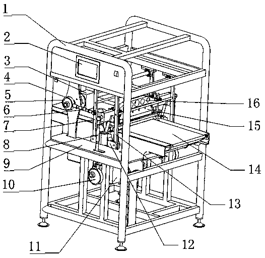
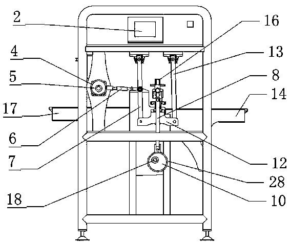
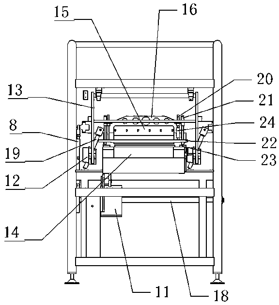
[0034] Such as Figure 1 to Figure 4 As shown, a six-axis cutting machine includes a frame 1. The frame 1 includes a plurality of columns and a plurality of beams. The columns of the frame are vertically arranged with the beams. The columns include four main columns and a plurality of branch columns. Three-layer beams are arranged between the four main columns, and the three-layer beams include a lower beam, a middle beam and an upper beam, and multiple branch beams are arranged in each layer beam. A conveying device and a cutting device are installed on the frame 1, and the conveying device is used for feeding and outputting materials.

[0035] The block cutting device includes a cutter mechanism, a block cutting power mechanism, two groups of symmetrically arranged block cutting transmission mechanisms and two groups of guide mechanisms, and the cutter mechanism is arranged on the upper part of the conveying device. The cutting power structure includes a first motor 11, the...

Embodiment 2

[0047] Such as Figure 5 to Figure 6 As shown, the structure of this embodiment is basically the same as that of Embodiment 1, the difference is that the cutting power mechanism and the cutting transmission mechanism in this embodiment are different, specifically, the cutting power mechanism includes a first motor 11 , the first motor 11 is arranged on the top of the tool rest 16, the first motor 11 is connected to the first power shaft, the first motor 11 drives the first power shaft to rotate, the first power shaft is connected with the first eccentric wheel 10, the first eccentric wheel 10 The center line of the first power shaft is set eccentrically with the center line of the first power shaft. The outer circular surface of the first eccentric wheel 10 is sleeved with a first collar 28. The first eccentric wheel 10 can rotate relative to the first collar 28. The first set The outer circular surface of the ring 28 is fixedly connected with a first connecting rod 29, and on...


PUM


Abstract

The invention relates to the technical field of food processing equipment, in particular to a six-axis type dicing machine. The six-axis type dicing machine comprises a rack. A conveying device and adicing device are mounted on the rack. The dicing device comprises a cutting knife mechanism, a dicing power mechanism, dicing transmission mechanisms and guide mechanisms. The dicing power mechanismis connected with the dicing transmission mechanisms. The dicing transmission mechanisms are connected with the cutting knife mechanism. The cutting knife mechanism is arranged on the upper portion ofthe conveying device and comprises a knife holder, and the lower portion of the knife holder is connected with a cutting knife. The dicing transmission mechanisms are connected with the knife holder.The two ends of the knife holder are each connected with one set of guide mechanism. Each guide mechanism comprises a guide shaft and a guide plate. According to the six-axis type dicing machine, itis guaranteed that the cutting knife cuts off materials rapidly and effectively, levelness of the cutoff positions of the materials is improved, and it is guaranteed that the candy dicing quality is guaranteed.

Description

technical field [0001] The invention relates to the technical field of food processing equipment, in particular to a six-axis cutting machine. Background technique [0002] The candy manufacturing process includes tableting, slitting, cutting and other processes. [0003] Among them, during the cutting process, the strip-shaped material is continuously conveyed to the position of the cutter by the conveyor belt, and cut into pieces by the cutter, and then sent out by the conveyor belt after the cutting is completed. Because the candy is sticky and tough, and the raw material has a certain thickness, the existing cutting knife can only move up and down and forward and backward, and the cutting knife cannot cut the raw material quickly and effectively. The phenomenon of uneven cutting, the edge of the cut candy is not neat, which affects the appearance of the candy after cutting. Therefore, in order to solve this problem, it is necessary to invent a cutter mechanism that can ...

Claims


Application Information

Patent Timeline
Patent Type & Authority Applications(China)
IPC IPC(8): B26D3/20B26D1/60B26D7/06B26D5/16B26D7/18
CPCB26D3/20B26D1/60B26D7/0625B26D5/16B26D7/1836B26D2210/02
Inventor 魏志刚
Owner DONGYING ZHIDA FOOD MACHINERY
Learn More