
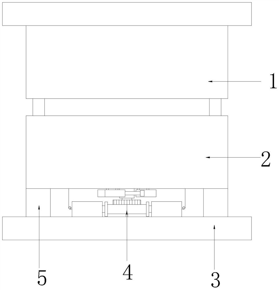
An automatic ejector injection molding mold for a table support frame

A technology of injection molding and support frame, which is applied to household appliances, other household appliances, household components, etc. It can solve the problems of marks on injection moulded parts, bubbles in plastic parts, and difficult to control, so as to avoid bubbles, ensure quality, and prevent marks from leaving marks. Effect

Active Publication Date: 2021-05-25
山东嘉华新能源开发有限公司
View PDF6 Cites 0 Cited by
  • Summary
  • Abstract
  • Description
  • Claims
  • Application Information

AI Technical Summary

Problems solved by technology

[0004] 1) Because the upper and lower molds are made of solid steel, when the mold is closed, the contact surface of the upper mold and the lower mold will collide rigidly, which will easily cause the wear of the upper and lower molds, and the upper and lower molds after mold closing will be easily damaged for a long time. There are gaps between the molds, which will cause air to enter during injection molding, so that the plastic parts will generate air bubbles, which will affect the strength of the injection molded parts;
[0005] 2) Most of the plastic parts are ejected by manually pushing the top plate and ejector pin to eject, that is, the ejection process requires manual assistance to demould, which is low in efficiency, and because the residual temperature of the plastic remains after molding, the force of manually pushing the top plate and ejector pin is relatively high. Difficult to control. If the force is too large, stress will be generated, which will easily leave marks on the injection molded parts, which will affect the quality of the injection molded parts. If the force is too small, the injection molded parts cannot be ejected quickly.

Method used


Image

  • An automatic ejector injection molding mold for a table support frame
  • An automatic ejector injection molding mold for a table support frame
  • An automatic ejector injection molding mold for a table support frame

Examples


Embodiment Construction

[0035] The following will clearly and completely describe the technical solutions in the embodiments of the present invention with reference to the accompanying drawings in the embodiments of the present invention. Obviously, the described embodiments are only some, not all, embodiments of the present invention. Based on the embodiments of the present invention, all other embodiments obtained by persons of ordinary skill in the art without making creative efforts belong to the protection scope of the present invention.

[0036] In the description of the present invention, it should be noted that unless otherwise specified and limited, the terms "connected" and "connected" should be understood in a broad sense, for example, it can be a fixed connection, a detachable connection, or an integral Ground connection; it can be mechanical connection or electrical connection; it can be direct connection or indirect connection through an intermediary. Those of ordinary skill in the art ...


PUM


Abstract

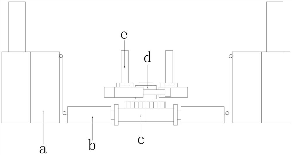
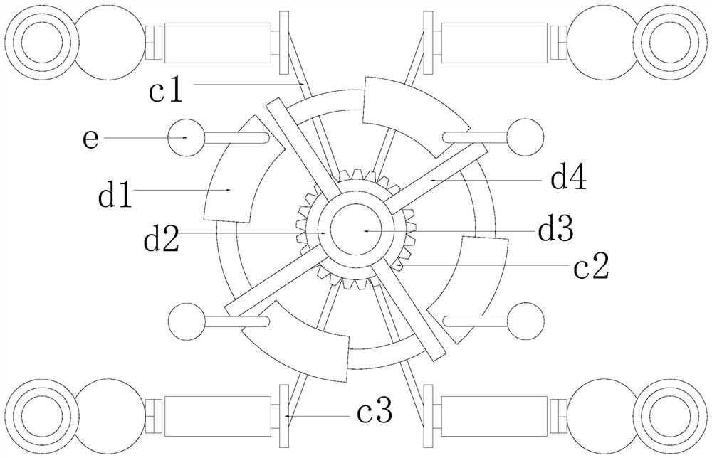
The invention discloses an injection molding mold for automatic topping of a table support frame. The structure includes an upper mold, a lower mold, a base, an ejection mechanism, and a connecting block. Compared with the prior art, the present invention has the beneficial effect of connecting the connecting block with the base: through the combined setting of the positioning slow-falling group, the telescopic group, the scissors and forks, the plastic part ejection power group, and the plastic part ejection group, so that The upper mold can fall slowly to avoid rigid collision with the lower mold when the mold is closed, so as to prevent damage to the upper and lower molds and avoid gaps between the upper and lower molds. No air will enter during injection molding, which can avoid air bubbles in the plastic parts. The strength of the plastic parts can be guaranteed, and the process of ejecting the injection molded parts is more stable, without manual assistance, with high efficiency and balanced force. It can quickly eject the injection molded parts and effectively prevent the ejector plate from leaving marks on the plastic parts. So that the quality of plastic parts can be guaranteed.

Description

technical field [0001] The invention relates to the technical field of moulds, in particular to an injection molding mold for automatic ejection of a table support frame. Background technique [0002] The bottom supporting frame of an existing combined plastic table is X-shaped, which is to obtain a molded product by injecting heated and melted plastic into a mold cavity under high pressure from an injection molding machine, and then cooling and solidifying it. [0003] Due to the imperfect technology, the existing injection molding molds have the following defects to be improved: [0004] 1) Because the upper and lower molds are made of solid steel, when the mold is closed, the contact surface of the upper mold and the lower mold will collide rigidly, which will easily cause the wear of the upper and lower molds, and the upper and lower molds after closing the mold will be easily damaged for a long time. There are gaps between the molds, which will cause air to enter durin...

Claims


Application Information

Patent Timeline
Patent Type & Authority Patents(China)
IPC IPC(8): B29C45/26B29C45/40B29L31/44
CPCB29C45/26B29C45/4005B29L2031/448
Inventor 陈宇庄爱妹
Owner 山东嘉华新能源开发有限公司
Learn More