Path planning method, system and equipment for intelligent equipment as well as readable storage medium

A technology of intelligent equipment and path planning, which is applied in the direction of road network navigators, measuring devices, instruments, etc.

Active Publication Date: 2019-10-25
BEIJING JINGDONG QIANSHITECHNOLOGY CO LTD
View PDF20 Cites 5 Cited by
  • Summary
  • Abstract
  • Description
  • Claims
  • Application Information

AI Technical Summary

Problems solved by technology

[0003] The technical problem to be solved by the embodiments of the present invention is to overcome the defect that the path planning in the prior art depends on the pre-built environment model and the positioning of the robot itself, and provide a path planning method, system, device and readable storage medium for smart devices

Method used


Image

  • Path planning method, system and equipment for intelligent equipment as well as readable storage medium
  • Path planning method, system and equipment for intelligent equipment as well as readable storage medium
  • Path planning method, system and equipment for intelligent equipment as well as readable storage medium

Examples


Embodiment 1

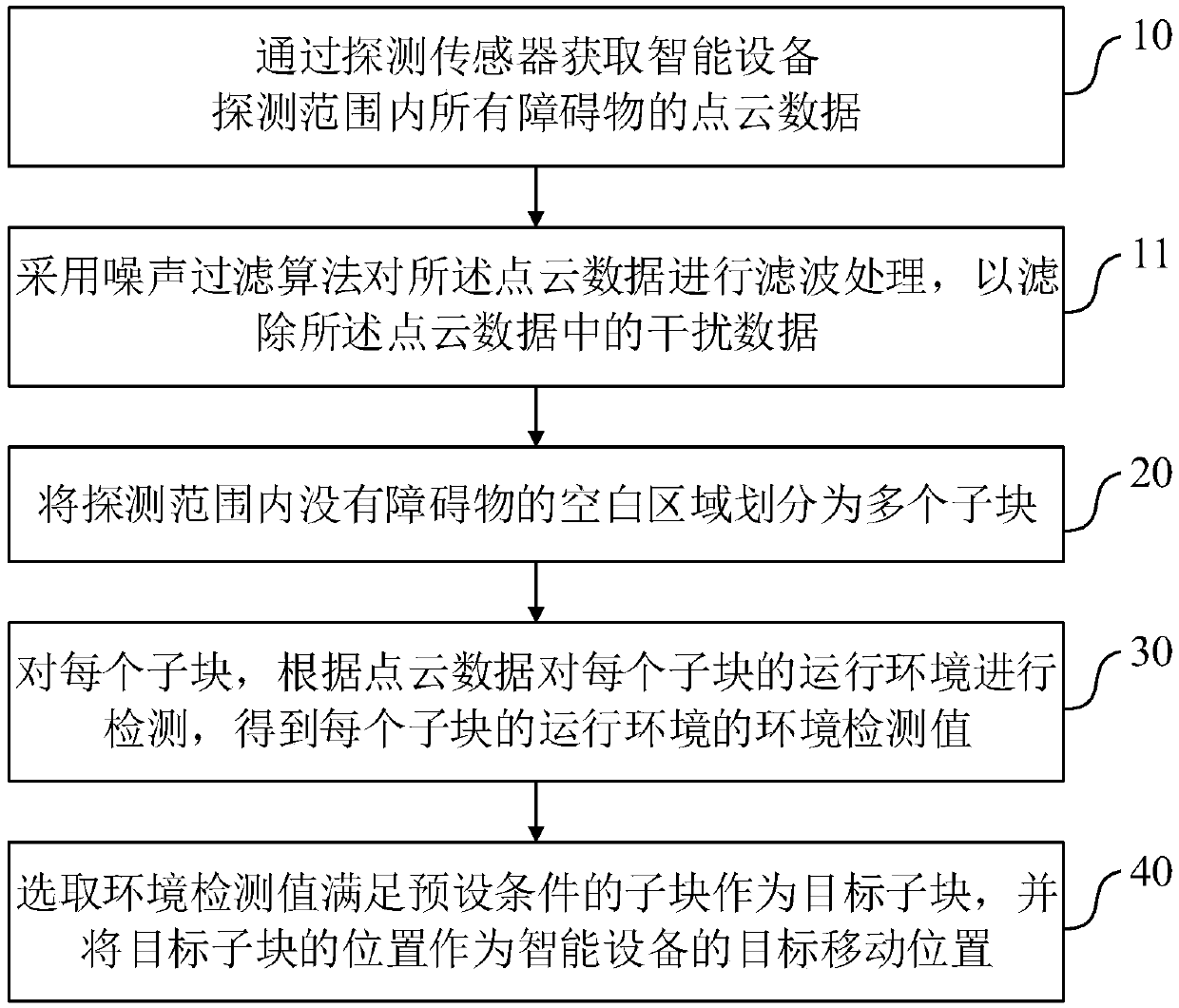
[0090] A path planning method for smart devices, such as figure 1 As shown, the path planning method includes:

[0091] Step 10. Obtain point cloud data of all obstacles within the detection range of the smart device through a detection sensor; the detection sensor is used to obtain point cloud data with depth information, and the detection sensor includes a binocular camera, an RGBD camera, an infrared camera, At least one of a multi-line laser and a single-line laser.

[0092] Step 20, divide the blank area without obstacles within the detection range into a plurality of sub-blocks; the area of ​​the sub-blocks is not smaller than the floor area of ​​the smart device;

[0093] Step 30, for each sub-block, detect the operating environment of each sub-block according to the point cloud data, and obtain the environmental detection value of the operating environment of each sub-block;

[0094] Step 40: Select a sub-block whose environment detection value satisfies a preset con...

Embodiment 2

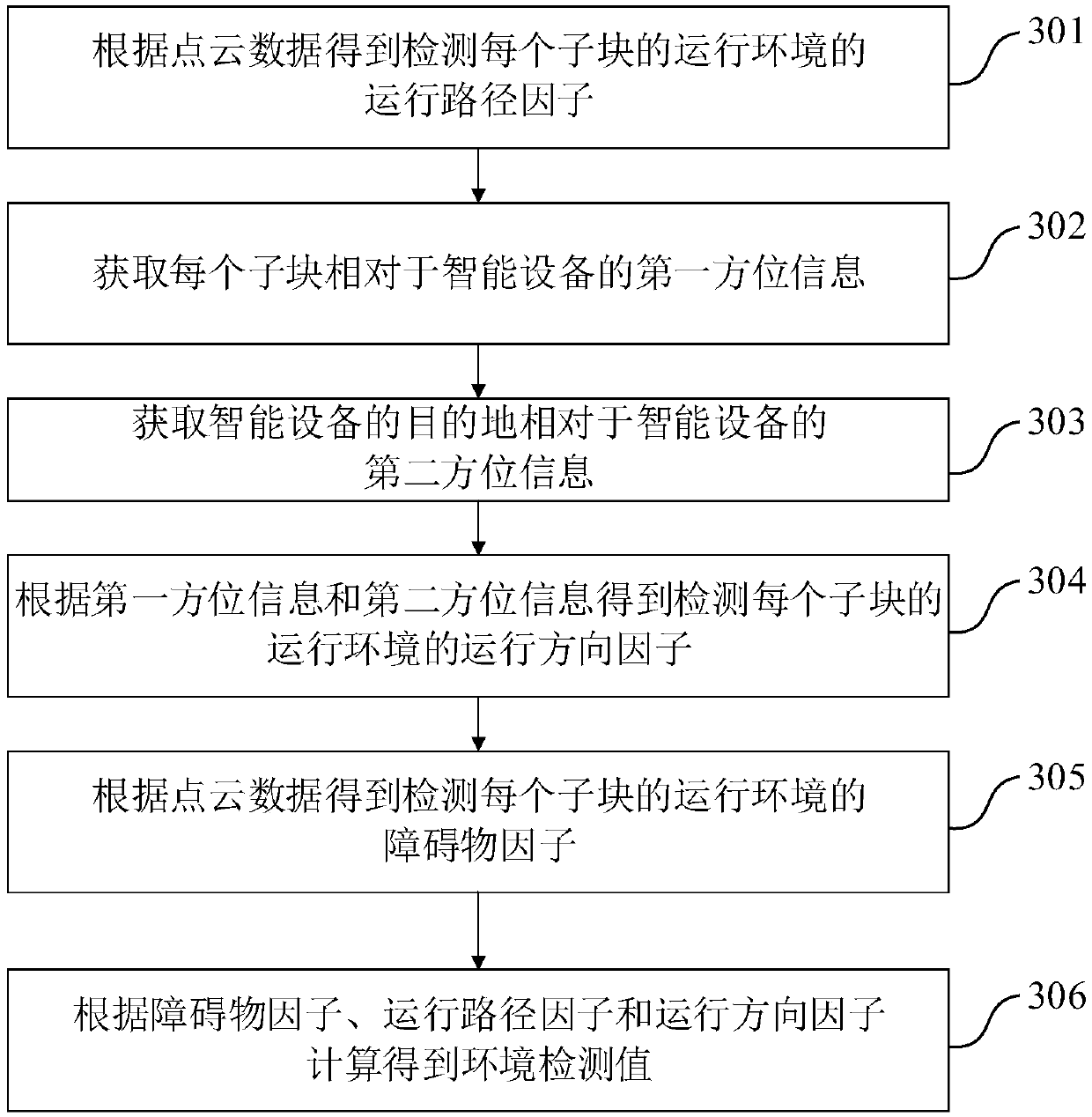
[0100] The path planning method of the smart device in this embodiment is further improved on the basis of Embodiment 1, such as figure 2 As shown, step 30 specifically includes:

[0101] Step 301. Obtain the operating path factor for detecting the operating environment of each sub-block according to the point cloud data; the operating path factor includes the distance information and / or the distance information between the moving path of the smart device to each sub-block and each obstacle. The width of the running path;

[0102] Step 302, obtaining the first orientation information of each sub-block relative to the smart device;

[0103] Step 303, acquiring the second orientation information of the destination of the smart device relative to the smart device;

[0104] Step 304, obtain the running direction factor for detecting the running environment of each sub-block according to the first orientation information and the second orientation information; the running direct...

Embodiment 3

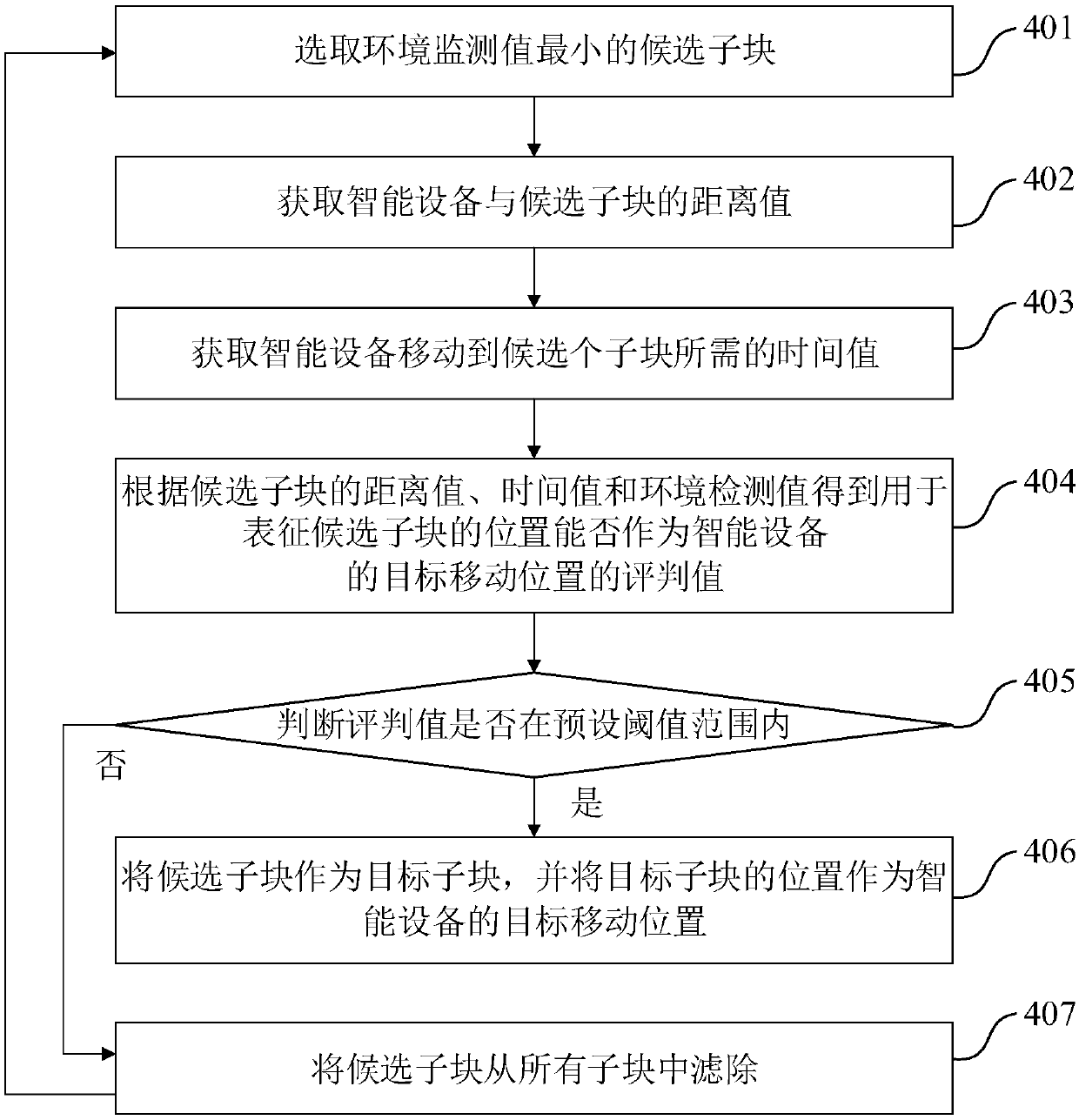
[0125] The path planning method of the smart device in this embodiment is further improved on the basis of Embodiment 1, such as image 3 As shown, step 40 specifically includes:

[0126] Step 401, selecting the candidate sub-block with the smallest environmental monitoring value;

[0127] Step 402, obtaining the distance value between the smart device and the candidate sub-block;

[0128] Step 403, obtaining the time value required for the smart device to move to the candidate sub-block;

[0129] Step 404, according to the distance value, time value and environment detection value of the candidate sub-block, obtain the evaluation value used to represent whether the position of the candidate sub-block can be used as the target mobile position of the smart device;

[0130] Step 405, judging whether the evaluation value is within the preset threshold range, if yes, execute step 406; if not, execute step 407;

[0131] Step 406, taking the candidate sub-block as the target sub-...


PUM


Abstract

The invention discloses a path planning method, system and equipment for intelligent equipment as well as a readable storage medium. The path planning method comprises the following steps: acquiring point cloud data of all the obstacles in a detection range of the intelligent equipment by virtue of a detection sensor; dividing a blank area containing no obstacle in the detection range into multiple sub blocks, wherein the area of each sub block is not smaller than occupied area of the intelligent equipment; for each sub block, detecting an operating environment of each sub block according to the point cloud data, and obtaining an environment detection value of the operating environment of each sub block; selecting the sub block with the environment detection value meeting preset conditionsas a target sub block, and taking a position of the target sub block as a target shifting position of the intelligent equipment. The method disclosed by the invention acquires the point cloud data ofthe obstacles in real time by virtue of the detection sensor and divides the blank area in the detection range, real-time operating environment detection on each sub block is performed, and further the target shifting position of the intelligent equipment is selected by virtue of the environment detection value.

Description

technical field [0001] The invention belongs to the field of path planning of intelligent equipment, and in particular relates to a path planning method, system, equipment and readable storage medium of intelligent equipment. Background technique [0002] Path planning is to reasonably plan a drivable path from the starting point to the end point according to the environmental information. For the path planning of intelligent devices, such as intelligent robots, the existing methods generally need to collect environmental information in advance and establish a map that can map the actual situation. The environment model, and then use the corresponding algorithm to search for a passable path based on the environment model. However, once the constructed environment information is incomplete or the accuracy is not high, the environment information that could have been used as a reference will become the interference of planning, such as: If the position of obstacles in the actu...

Claims


Application Information

Patent Timeline
Patent Type & Authority Applications(China)
IPC IPC(8): G01C21/20G01C21/34
CPCG01C21/20G01C21/3461
Inventor 哈融厚吴迪黄玉玺董秋伟
Owner BEIJING JINGDONG QIANSHITECHNOLOGY CO LTD
Why Eureka
Try Eureka