A test device and method for measuring the displacement field of soil around a loaded structure

A technology of the surrounding soil and test equipment, applied in the direction of measuring equipment, testing material strength by applying stable shear force, testing material strength by applying stable tension/compression, etc., can solve the problem of low accuracy of measurement results and insufficient displacement Continuity and other issues to achieve the effect of avoiding displacement jump and load fluctuation, simple structure setting, and preventing irregular deflection

Active Publication Date: 2020-06-02
SHANDONG HUAJIAN ENG TESTING CO LTD
View PDF6 Cites 0 Cited by
  • Summary
  • Abstract
  • Description
  • Claims
  • Application Information

AI Technical Summary

Problems solved by technology

[0004] In order to overcome the deficiencies of the prior art, the present invention provides a test device for measuring the displacement field of the soil around the loaded structure, which adopts the method of displacement loading, which can realize the uniform application of deformation displacement, and solve the problem of discontinuous application of displacement and The technical problem of low accuracy of measurement results has the advantage of being able to be used repeatedly

Method used


Image

  • A test device and method for measuring the displacement field of soil around a loaded structure

Examples


Embodiment 1

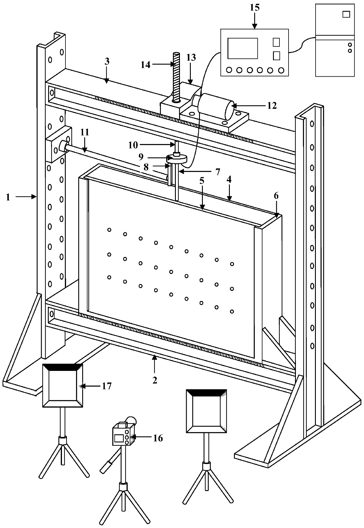
[0038] In a typical embodiment of the present invention, such as figure 1 As shown, a test device for measuring the displacement field of the soil around the loaded structure includes a bracket, a plane strain model groove, a loading mechanism and a recording mechanism.

[0039] The bracket, the bracket includes fixed supports 1 on both sides, and the fixed supports 1 on both sides are arranged at intervals of a set distance, and the bottom support beam 2 and the top reaction beam 3 parallel to each other are supported by the fixed support 1, and the bottom support beam 2 and The top reaction beam 3 is thickened I-beam, the width of both is 0.2m, the length is 1.2-1.8m, and the maximum applied reaction force of the top reaction beam is 1t.

[0040] The upper part of the bottom support beam 2 is connected to the plane strain model groove, and the two sides of the bottom support beam 2 are connected to the fixed support 1 by bolts; the top reaction beam 3 supports the loading me...

Embodiment 2

[0047] A test method for measuring the displacement field of soil around a loaded structure, using the test device for measuring the displacement field of soil around a loaded structure as described in Embodiment 1, specifically including the following:

[0048] First, determine the size of the plane strain model slot and the relative heights of the bottom support beam 2 and the top reaction beam 3 according to the research object;

[0049] Install the bottom support beam 2 and the top reaction beam 3 on the fixed support 1;

[0050] After splicing the front baffle and rear baffle of the plane strain model groove and the side soil retaining panels on both sides, they are set on the bottom support beam 2 and fixed by bolts. The displacement reference point is set by a paint pen on the front baffle 5;

[0051] Fill and compact the plane strain model groove, install the structure and the second connecting rod 7 after reaching the set height, one end of the second connecting rod ...


PUM

PropertyMeasurementUnit
heightaaaaaaaaaa
thicknessaaaaaaaaaa

Abstract

The invention discloses a measuring and testing device and a measuring and testing method for a soil mass displacement field around a loaded structure. The measuring and testing device and the measuring and testing method solve the problem of discontinuous displacement application in the prior art, and have the beneficial effects that the measurement precision is high and the model can realize repeated use. The measuring and testing device is characterized in that: the measuring and testing device for the soil mass displacement field around the loaded structure comprises a bracket, a plane strain model tank, a loading mechanism and a recording mechanism, wherein the plane strain model tank supported by means of the bracket, at least one side surface of the plane strain model tank is transparent, the plane strain model tank is filled with a filler, structures are embedded inside the filler, the structures are connected with one end of a connecting rod; the loading mechanism is supportedby means of the bracket, the loading mechanism comprises a lifting component capable of realizing up and down lifting motion, a stress sensor is arranged between the lifting component and the other end of the connecting rod, and a displacement sensor is supported by means of the fixed bracket; and the recording mechanism is arranged on at least one side of the plane strain model tank for recording the displacement changes of the filler in the plane strain model tank.

Description

technical field [0001] The invention relates to the field of soil displacement field observation, in particular to a test device and method for measuring the displacement field of soil around a load-bearing structure. Background technique [0002] When the structures embedded in the soil (such as pile foundations, shallow foundations, anchor cables / slabs, oil pipelines, etc.) are subjected to external loads, the soil around the structures will be compressed or sheared to resist external loads. role. After the structure is stressed, the weight of the surrounding soil, the distribution form and length of the fracture surface directly determine the bearing capacity of the structure. Therefore, the study of the distribution of the displacement field of the soil around the structure has important guiding significance for the derivation of the calculation theory of the bearing capacity of the structure and the design and calculation of the ultimate bearing capacity. [0003] At ...

Claims


Application Information

Patent Timeline
Patent Type & Authority Patents(China)
IPC IPC(8): G01N3/08G01N3/24
CPCG01N3/08G01N3/24G01N2203/0016G01N2203/005G01N2203/0075G01N2203/0284G01N2203/0676G01N2203/0682
Inventor 臧亚囡商淑杰万洋韩烨任士朴周仲张斌盛圆圆孙爱芬李志双孙鹏范吉高张思峰张素磊
Owner SHANDONG HUAJIAN ENG TESTING CO LTD
Why Eureka
Try Eureka