
A photovoltaic control method, device, device and computer-readable storage medium

A photovoltaic control and photovoltaic technology, applied in the direction of circuit devices, photovoltaic power generation, AC network circuits, etc., can solve the problems of inability to coordinate system schedulable resources, large computing burden, and reduce the amount of communication information

Active Publication Date: 2021-03-12
ELECTRIC POWER RESEARCH INSTITUTE, CHINA SOUTHERN POWER GRID CO LTD +1
View PDF7 Cites 0 Cited by
  • Summary
  • Abstract
  • Description
  • Claims
  • Application Information

AI Technical Summary

Problems solved by technology

Among them, centralized control is based on global information for global optimization, but the rapid increase of photovoltaics greatly increases the communication burden and data processing pressure, and once the central controller fails, it cannot coordinate a large number of schedulable resources in the system. In addition, In consideration of privacy and security, it is difficult for centralized control to obtain global information accurately and conveniently; local control only relies on local measurement information for control, although it cannot achieve global optimization, it does not require information exchange and remote measurement between nodes , therefore, the amount of communication information is significantly reduced, and when the power fluctuates in the system, the local control can respond quickly and quickly stabilize the fluctuation. In-place control strategies impose a heavy computational burden
That is, the existing centralized control has the problem of a relatively large amount of communication information, while the existing local control has the problem of being unable to achieve global optimization and the computational burden is relatively large

Method used


Image

  • A photovoltaic control method, device, device and computer-readable storage medium
  • A photovoltaic control method, device, device and computer-readable storage medium
  • A photovoltaic control method, device, device and computer-readable storage medium

Examples


Embodiment Construction

[0060] The following will clearly and completely describe the technical solutions in the embodiments of the present invention with reference to the accompanying drawings in the embodiments of the present invention. Obviously, the described embodiments are only some, not all, embodiments of the present invention. Based on the embodiments of the present invention, all other embodiments obtained by persons of ordinary skill in the art without making creative efforts belong to the protection scope of the present invention.

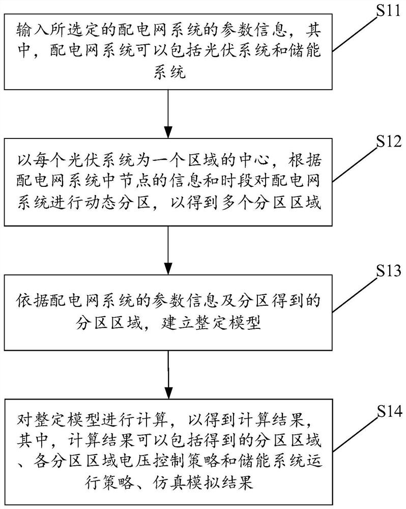
[0061] see figure 1 , which shows a flowchart of a photovoltaic control method provided by an embodiment of the present invention, which may include:

[0062] S11: Input parameter information of the selected distribution network system, wherein the distribution network system may include a photovoltaic system and an energy storage system.

[0063] Select the distribution network system to be controlled and include the photovoltaic system and the energy storag...


PUM


Abstract

The invention discloses a photovoltaic control method, device, equipment and computer-readable storage medium. The method includes: inputting the parameter information of the selected distribution network system; taking each photovoltaic system as the center of a region, according to the distribution The distribution network system is dynamically partitioned according to the node information and time periods in the network system to obtain multiple partition areas; the tuning model is established based on the parameter information of the distribution network system and the partition areas obtained by partitioning; the tuning model is calculated to obtain Get the calculation result. The above-mentioned technical solution disclosed in this application first dynamically partitions the distribution network system, and then treats the same type of photovoltaic system in the same partition area as a photovoltaic cluster and uses the same voltage control strategy and energy storage system operation strategy to control, In order to combine the advantages of centralized control and local control, it can not only reduce the amount of communication information, but also achieve global optimization between partitioned areas, and can reduce the computational burden.

Description

technical field [0001] The present invention relates to the technical field of distributed power supply control, and more specifically, to a photovoltaic control method, device, equipment and computer-readable storage medium. Background technique [0002] While the access of distributed power sources such as photovoltaics in the distribution network system brings good economic and environmental benefits, it also causes large fluctuations in feeder power, unbalanced power between feeders, and Voltage limit and many other problems. [0003] At present, the distributed power source of photovoltaic in the distribution network system is mainly realized by centralized control or local control. Among them, centralized control is based on global information for global optimization, but the rapid increase of photovoltaics greatly increases the communication burden and data processing pressure, and once the central controller fails, it cannot coordinate a large number of schedulable ...

Claims


Application Information

Patent Timeline
Patent Type & Authority Patents(China)
IPC IPC(8): H02J3/38
CPCH02J3/383H02J2203/20Y02E10/56
Inventor 于力陈柔伊白浩史训涛姜臻黄彦璐郭志诚王琦张斌
Owner ELECTRIC POWER RESEARCH INSTITUTE, CHINA SOUTHERN POWER GRID CO LTD
Learn More