Surface rough grinding device for gear processing

A gear and coarse grinding technology, which is applied in gear tooth manufacturing devices, metal processing equipment, belts/chains/gears, etc., can solve the problems of low grinding efficiency and affecting processing speed, so as to improve service life, save resources and avoid side effects. Partial effect

Inactive Publication Date: 2019-10-29
SHIYAN TONGLU IND
View PDF0 Cites 1 Cited by
  • Summary
  • Abstract
  • Description
  • Claims
  • Application Information

AI Technical Summary

Problems solved by technology

[0004] During gear production, it is necessary to carry out rough grinding and fine grinding on the gear end face and shaft surface. The existing rough grinding device has low grinding efficiency, which affects the processing speed.

Method used


Image

  • Surface rough grinding device for gear processing
  • Surface rough grinding device for gear processing
  • Surface rough grinding device for gear processing

Examples


Embodiment 1

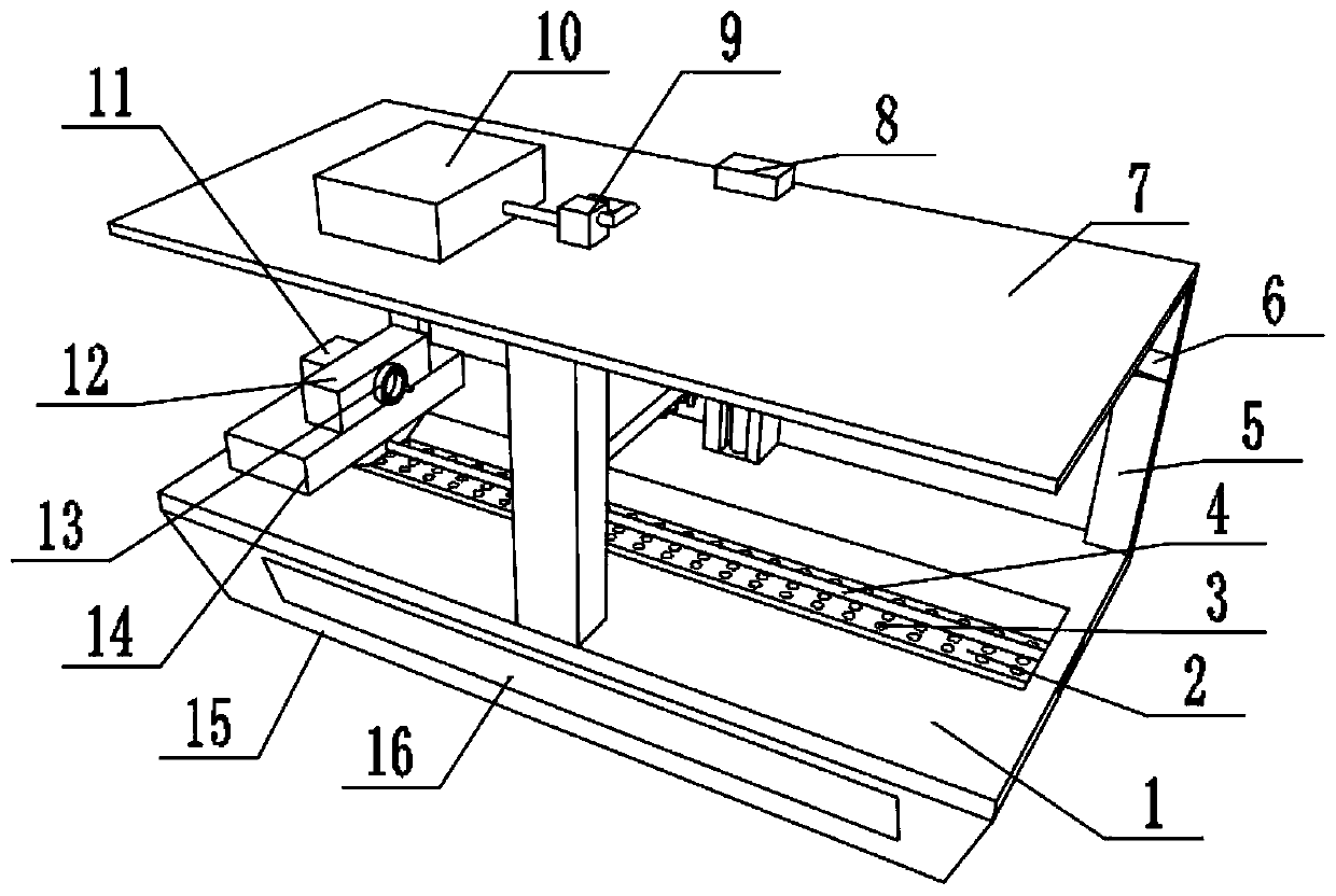
[0028] refer to Figure 1-3 , a surface rough grinding device for gear processing, comprising a workbench 1, columns 5 are welded on both sides of the top of the workbench 1, and the top outer walls of the two columns 5 are welded with the same top seat 7, the top Both sides of the bottom of the seat 7 are provided with a rough sharpening mechanism, and the top of the top seat 7 is provided with a cooling mechanism; the top of the workbench 1 has a groove 2, and a No. 1 screw 4 is fixed in the groove through a bearing. The outer wall of the No. 1 leading screw 4 is threadedly connected with a sliding seat 14, and the top of the sliding seat 14 is provided with a gear workpiece clamping mechanism.

[0029] Wherein, the rough sharpening mechanism includes a fixed frame welded on both sides of the bottom end of the top base 7, and a No. 2 lead screw is fixed by a bearing in the fixed frame, and a No. 1 motor 8 is fixed on one side of the top base 7 by screws. The output shaft of...

Embodiment 2

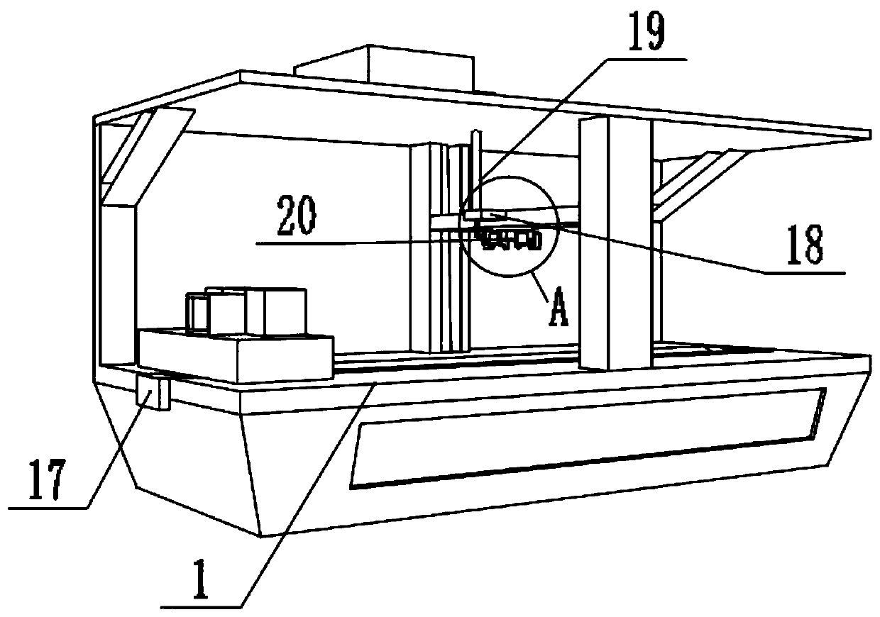
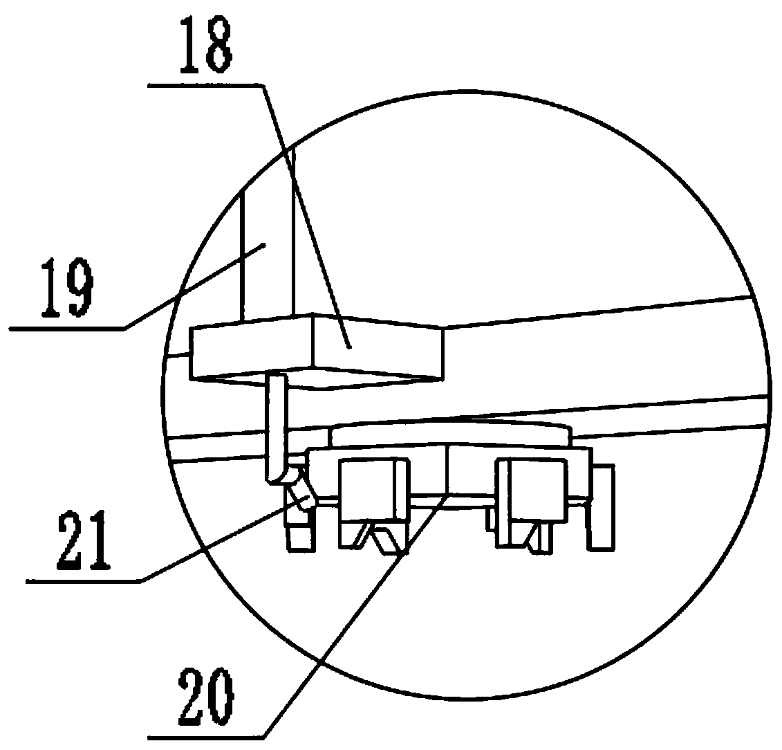
[0035] refer to image 3 , a surface rough grinding device for gear processing. In order to improve the energy-saving and environmental protection effect of the equipment, this embodiment makes the following improvements on the basis of embodiment 1: the inner walls on both sides of the groove 2 are inclined inward, and the groove There are several through-holes 3 in 2; the bottom of the workbench 1 is welded with a bottom box 15, and the side wall of the bottom box 15 is provided with a side cover 16; the cooling liquid sprayed by the nozzle 21 can flow into the In the bottom box 15, the coolant can be recovered, which is energy-saving and environment-friendly.

[0036] The working principle of this embodiment: during rough grinding, the nozzle 21 sprays coolant into the groove 2, and the inclined inner wall guides the liquid into the through hole 3, and flows into the bottom box 15 for recycling.


PUM


Abstract

The invention discloses a surface rough grinding device for gear processing. The surface rough grinding device comprises a working table, wherein uprights are disposed on two sides of the top end of the working table; the same top base is disposed on outer walls of the top parts of the two uprights; rough grinding cutter mechanisms are disposed on two sides of the bottom end of the top base; a cooling mechanism is disposed on the top end of the top base; a groove is formed in the top end of the working table; a No.1 lead screw is fixed inside the groove via a bearing; a slide base is in threaded connection to the outer wall of the No.1 lead screw; and a gear workpiece clamping mechanism is disposed on the top end of the slide base. The device disclosed by the invention has the beneficial effects that different cutters can be installed through setting of an orthohexagonal cutter disk; the cutters can be replaced through rotation adjustment; operations are flexible and quick; the rough grinding cutter mechanism is supported by two fixation frames; through transmission of the two lead screws, stability of lifting motion of the cutters is enhanced; lateral deviation is avoided; a cooling liquid can be loaded in a liquid storage box and can be ejected from a shower nozzle to cool the cutters; and the service life of equipment is increased.

Description

technical field [0001] The invention relates to the technical field of gear processing, in particular to a surface rough grinding device for gear processing. Background technique [0002] A gear is a mechanical element with gears on the rim that continuously mesh to transmit motion and power. [0003] Compared with developed countries, China's gear manufacturing industry still has problems such as insufficient independent innovation capabilities, slow new product development, disorderly market competition, weak enterprise management, low degree of informatization, and the overall quality of employees needs to be improved; Most of them can be produced, and most of the high-end gear molds rely on imports. There are not many factories specializing in gear molds in China. Most of them make gear molds by themselves. Gear factories often set up a section or a workshop to undertake this work. This makes the development of the domestic gear mold industry even more difficult. [0...

Claims


Application Information

Patent Timeline
Patent Type & Authority Applications(China)
IPC IPC(8): B23F19/02B23F23/02B23Q11/10
CPCB23F19/02B23F23/02B23Q11/10
Inventor 王涛姚玉军王聪
Owner SHIYAN TONGLU IND
Why Eureka
Try Eureka