A fastener striking tool

A technology for striking tools and fasteners, which is applied in the direction of manufacturing tools and nailing tools, and can solve problems such as potential safety hazards, complex structures of elastic meshing parts, and damage to transmission parts

Active Publication Date: 2022-03-08
NANJING TENGYA PRECISE TECH DEV CO LTD
View PDF11 Cites 0 Cited by
  • Summary
  • Abstract
  • Description
  • Claims
  • Application Information

AI Technical Summary

Problems solved by technology

[0003] However, it has been found in practice that, in the above-mentioned existing nail gun operation, due to various reasons, when nails are stuck occasionally, such as figure 1 , figure 2 shown, whether the drive wheel is figure 1 The pinion drive shown, or figure 2 The gear transmission shown, because the striker 4 is blocked and does not move to figure 2 The normal limit position shown by the dot-dash line, so the gear teeth of the driving member 9 may interfere with the striker 4 when it is lifted again, that is, it is blocked and cannot enter the meshing state. parts, and because the air in the cylinder still has a certain pressure, once the staple is removed, the striker will move out of control, resulting in a safety hazard
[0004] For this reason, the technical solution disclosed in the U.S. patent literature with the application number US20180154505A1 attempts to solve the above-mentioned problems by providing an elastic engagement member on the drive wheel to avoid interference, but the elastic engagement member with a certain degree of freedom is not only complicated in structure, but also reliable. Poor sex
The 201621041199.3 patent also provided a pawl locking structure to prevent the striker from running out of control, but this not only increased the complexity of parts assembly and control

Method used


Image

  • A fastener striking tool
  • A fastener striking tool
  • A fastener striking tool

Examples


Embodiment 1

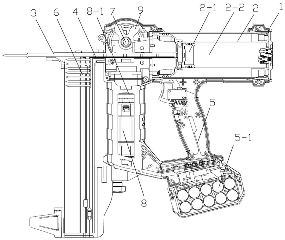
[0041] The basic structure of the fastener percussion tool in this embodiment can be found in image 3 The rear end of the housing 1 is equipped with an energy storage mechanism 2 composed of a cylinder 2-2 and a piston 2-1, and the piston 2-1 is fixedly connected with the firing pin 4 extending to the gun mouth 3. The lower side of the cylinder body 2-2 is provided with a handle 5 with a battery pack 5-1, the lower side of the gun nozzle 3 is provided with a nail box 6 for arranging nails, and a nail box 6 located between the handle 5 and the nail box 6 is provided on the top. The lifting mechanism 7 and the motor 8 and the reduction transmission mechanism 8-1 that are positioned at the bottom.

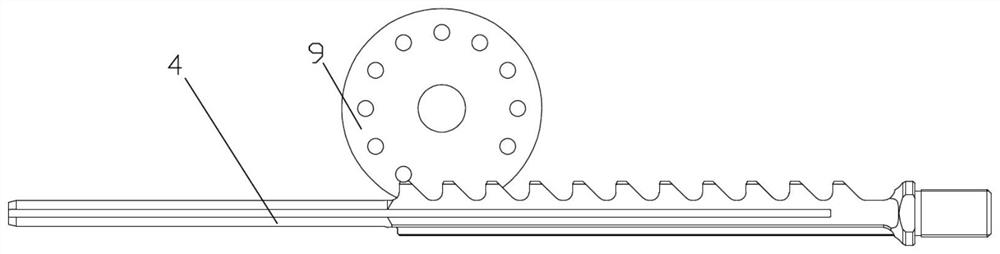
[0042] The concrete structure of hoisting mechanism 7 is as Figure 4 As shown, similar to the prior art, the lack of teeth that contains the clip gear structure that can force the striker 4 to move the compression piston 2-1 gives way to the drive wheel 9, and the axle of the drive...

Embodiment 2

[0050] The basic structure of the fastener percussion tool of this embodiment is the same as that of Embodiment 1, except that the rear end of the housing 1 is equipped with an energy storage mechanism 2, the piston 2-1 is fixedly connected with the firing pin 4 extending to the gun mouth 3, and the cylinder body 2 The underside of -2 is provided with a handle 5, the underside of the gun nozzle 3 is provided with a nail case 6, and between the handle 5 and the nail case 6 is provided with a lifting mechanism 7, a motor 8 and a reduction transmission mechanism 8-1; The lifting mechanism 7 contains a driving wheel that can force the striker to move and compress the piston 2-1 with missing teeth, and the axle of the driving wheel is connected with the motor 8 that the battery pack 5-1 provides electric energy through the reduction transmission mechanism 8-1.

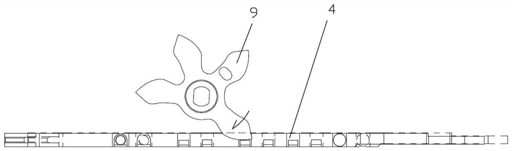
[0051] Such as Figure 11 As shown, what has changed is that the tooth-missing relief drive wheel is a tooth-to-pin struc...


PUM


Abstract

The invention relates to a fastener striking tool, which belongs to the technical field of electric tools. The tool includes an energy storage mechanism composed of a cylinder and a piston in the housing. The piston is fixedly connected with the firing pin extending to the gun mouth. One side of the cylinder is provided with a handle with a battery pack, and one side of the gun mouth is provided with a nail box. There is a lifting mechanism between the handle and the nail box; the lifting mechanism contains a driving wheel for missing teeth, and the driving wheel is connected to the motor; it also contains a transmission part that is looped on the firing pin; the transmission part has the function of forcing the firing pin to move when the driving wheel enters Before the state, it is in the first meshing position with the driving wheel; when the driving wheel enters the state of forcing the striker to move, the transmission part has a restraint structure combined with the striker; the transmission part has a tendency to reset to the first meshing position under the action of elasticity. After adopting the present invention, the normal meshing relationship between the driving wheel and the firing pin can be guaranteed all the time, effectively avoiding the possible meshing interference between the driving wheel and the firing pin due to the nail clamping, and ensuring safe operation.

Description

technical field [0001] The invention relates to a fastener striking tool, in particular to an electric gas spring nail gun, which belongs to the technical field of electric tools. Background technique [0002] As far as the applicant knows, for a long time, the tools used to fix one object to another object with the help of nail-type fasteners are mainly pneumatic tools, including high-pressure gas, gas combustion, etc., but these types of tools are either inconvenient to use, or High cost of use. For this reason, innovative electric gas spring nail guns have appeared in recent years. There are two types of typical structures. One is disclosed in US patents US8011441 and US8267296. The firing pin engaged with it stores energy by compressing the air in the cylinder through the piston. Another type of typical structure is disclosed in the Chinese patent document with application number 201621041199.3. This type of nail gun is driven by a motor with missing teeth to make way ...

Claims


Application Information

Patent Timeline
Patent Type & Authority Patents(China)
IPC IPC(8): B25C1/06
CPCB25C1/06
Inventor 常凤智高冬生朱清华王爱国徐朋
Owner NANJING TENGYA PRECISE TECH DEV CO LTD
Why Eureka
Try Eureka