Connecting structural component

A connection structure and integrated technology, applied in the direction of structural elements, building components, building reinforcements, etc., can solve problems affecting connection strength and connection stability, so as to ensure connection strength and reliability, improve connection strength, and avoid axial The effect of displacement

Active Publication Date: 2019-10-29
周兆弟
View PDF7 Cites 1 Cited by
  • Summary
  • Abstract
  • Description
  • Claims
  • Application Information

AI Technical Summary

Problems solved by technology

[0005] The purpose of the present invention is to solve the problem that when the existing connecting piece is subjected to axial tension or pressure, the conne

Method used


Image

  • Connecting structural component
  • Connecting structural component
  • Connecting structural component

Examples


Example Embodiment

[0051] In order to make the technical means, creative features, objectives and effects of the present invention easy to understand, the present invention will be further described with embodiments and accompanying drawings.

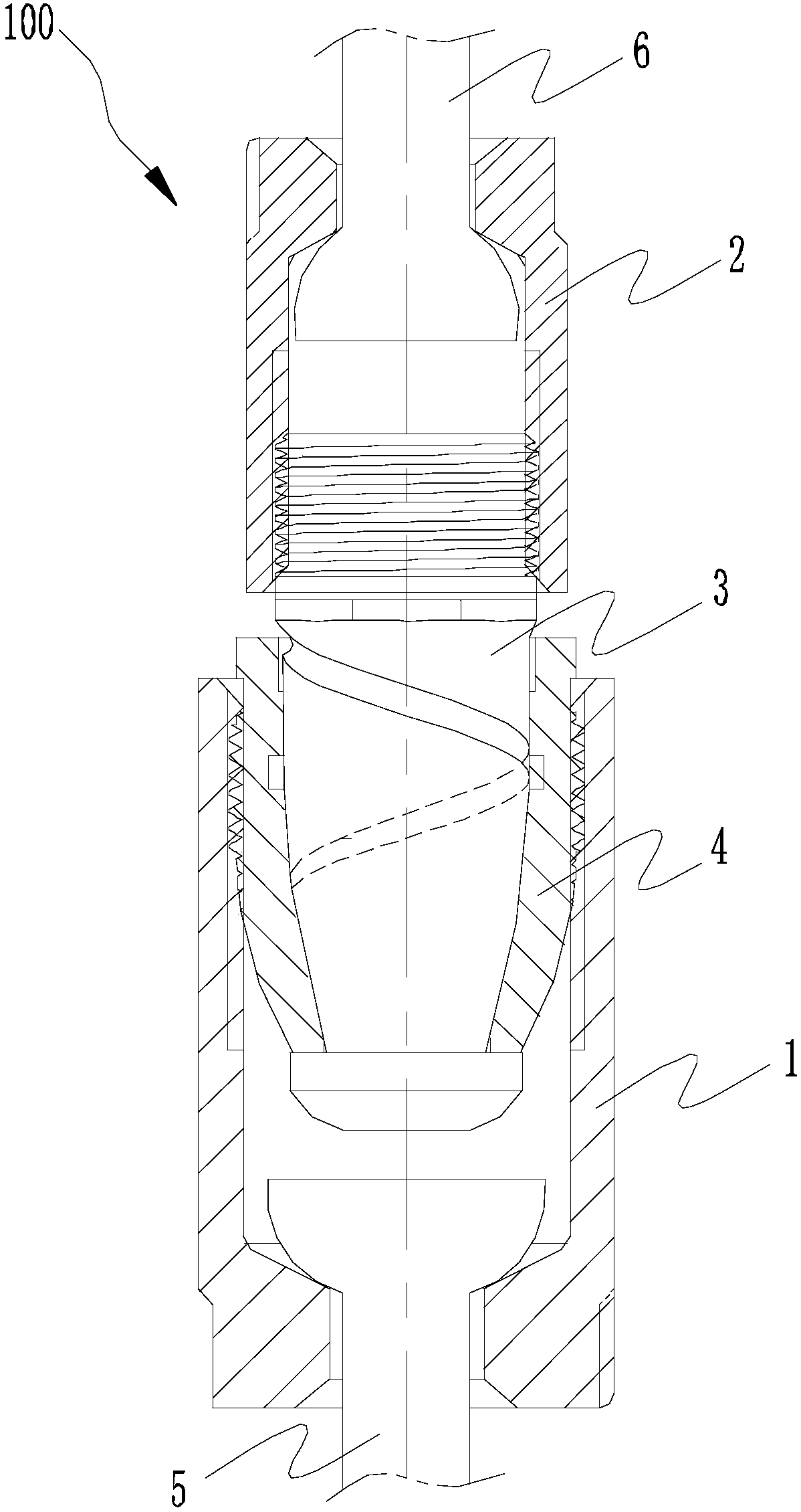
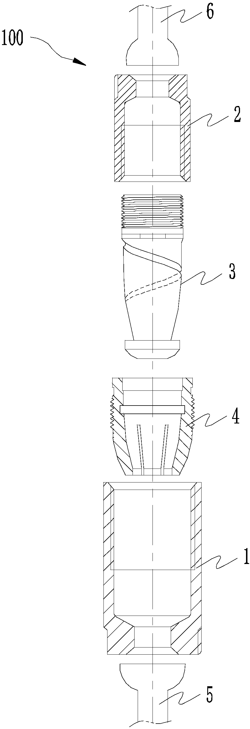
[0052] Such as figure 1 with figure 2 As shown, this embodiment provides a connecting structural member 100, which is used to connect two architectural prefabricated structural members (such as between piles and piles, between walls and walls, between piles and columns). , Or between the wall and the floor, etc.) in axially aligned or aligned rigid rods (such as steel bars, steel rods or any kind of strips that meet the requirements of rigidity and strength). Specifically, the connecting structure 100 includes: a first screw joint 1, a second screw joint 2, a plunger 3 and a collet 4.

[0053] Such as figure 1 , image 3 as well as Figure 4 As shown, in this embodiment, the first rigid bar 5 is embedded in a first preform not shown in the figure, and the fir...


PUM


Abstract

The invention discloses a connecting structural component. The connecting structural component comprises a first rotary connector, a second rotary connector, a collet chuck and an inserting rod. The collet chuck is provided with a rotary connection portion and a clamped connection portion. The first end of the inserting rod is in rotary connection with the second rotary connector, and the second end of the inserting rod penetrates through the rotary connection portion and then is in clamped connection with the clamped connection portion. At least one spiral groove is formed in the intermediateshaft section portion, between the first end and the second end, of the inserting rod, at least one groove is formed in the portion, on the inner wall face of the rotary connection portion, of the collet chuck in the circumferential direction, and when the second end of the inserting rod is in clamped connection with the clamped connection portion, the grooves communicate with the spiral grooves.The spiral grooves and the grooves can be filled with a liquid-state curing agent injected from the spiral grooves, the connecting strength between the connecting inserting rod and the collet chuck can be improved through the good bonding effect of the solidified curing agent, thus, the problem that the collet chuck is subjected to axial displacement relative to the inserting rod when the connecting structural part bears axial tension or pressure is avoided, and then the connecting strength and the reliability between two connected objects are guaranteed.

Description

technical field [0001] The invention relates to the field of construction engineering, in particular to a connection structure. Background technique [0002] The connector is a commonly used installation structure in the construction occasions such as between piles in pile foundation engineering, between walls in prefabricated houses, and between walls and floors. The structural strength and connection strength of the connector itself are related to the two The connection strength and connection stability between connected objects. [0003] For example, the Chinese invention patent (CN104947658B) discloses a snap-on connector, which includes a large nut sleeve, a small nut sleeve, a connector and an insertion rod. The aforementioned large nut sleeve is threadedly connected to the connector, wherein the connection There are multiple bent shrapnels in an annular array on one side of the big nut sleeve, and the angle between the bent shrapnel and the inner wall of the big nut ...

Claims


Application Information

Patent Timeline
IPC IPC(8): E04C5/16
CPCE04C5/165
Inventor 周兆弟
Owner 周兆弟
Why Eureka
Try Eureka