
Debugging method for improving failure working mode consistency of triplex-redundancy servo valves

A technology of working mode and debugging method, which is applied in the testing of fluid pressure actuating system, fluid pressure actuating device, mechanical equipment, etc., can solve the problems of once-faulted work performance decline, inconvenient debugging of servo system, and lack of in-depth research, etc. Improve debugging efficiency, facilitate parameter setting, and improve the effect of flow curve linearity

Active Publication Date: 2019-10-29
BEIJING RES INST OF PRECISE MECHATRONICS CONTROLS +1
View PDF10 Cites 5 Cited by
  • Summary
  • Abstract
  • Description
  • Claims
  • Application Information

AI Technical Summary

Problems solved by technology

The original three-redundancy servo valve has poor linearity and inconsistent performance when there are first-degree failures in different channels. However, due to the lack of delivery tasks, there is no in-depth research on the causes of the problems, so in order to get a better first-degree failure during debugging Working performance, it is often necessary to repeatedly adjust the flow gain of each pre-stage separately to ensure that the first-degree failure mode has good consistency and good performance. However, with the wide application of three-degree servo valves, this original no Targeted debugging methods cannot solve the problem quickly and efficiently. At the same time, due to the unknown mechanism of the problem, effective measures cannot be taken to improve it in design and process. It consumes a lot of time and cost, and it is easy to cause a serious delay in the delivery schedule under the condition of tight batch production tasks

Method used


Image

  • Debugging method for improving failure working mode consistency of triplex-redundancy servo valves
  • Debugging method for improving failure working mode consistency of triplex-redundancy servo valves
  • Debugging method for improving failure working mode consistency of triplex-redundancy servo valves

Examples


Embodiment Construction

[0034] The technical solutions of the present invention will be clearly and completely described below in conjunction with the drawings and specific implementation methods of the present invention.

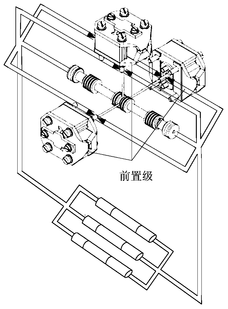
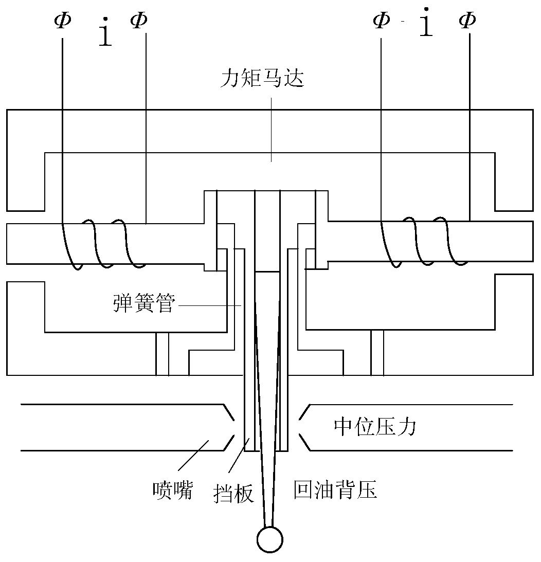
[0035] Such as figure 1 Shown is the schematic diagram of the structure of the three-redundancy servo valve, such as figure 2 Shown is the schematic diagram of the servo valve pre-stage structure.

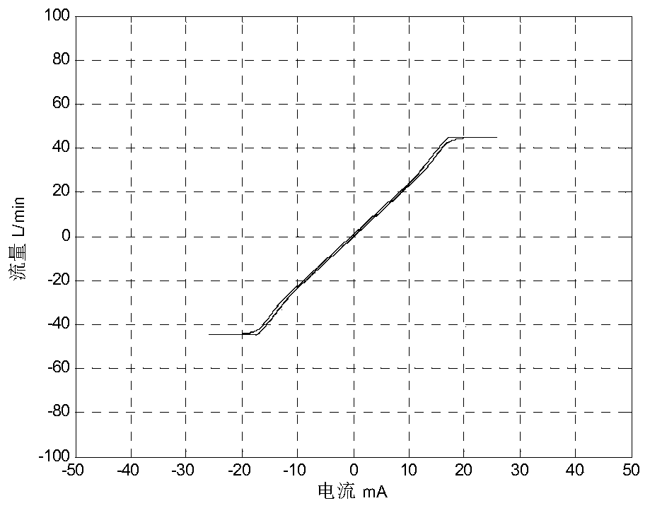
[0036] 1. When the fault flow curve of the redundant servo valve is saturated once, the saturated flow rate is significantly reduced, even lower than two-thirds of the normal working state, and the rated saturated flow rate is set to 84L / min, such as image 3 As shown, the saturated flow rate is reduced to 45L / min. At this point, perform debugging to increase the saturation flow in the fault state.

[0037] Debugging step 1: Improve the jet shape of the nozzle hole, screen out nozzles that do not scatter and concentrate the jet, and avoid self-excitation when the median pressure is...


PUM


Abstract

The invention discloses a debugging method for improving the failure working mode consistency of triplex-redundancy servo valves. The debugging method comprises the following steps of (1) conducting debugging to improve the failure state saturation flow before starting of first-redundancy failure debugging or when the first-redundancy failure flow curve of the redundancy servo valves is saturatedand the saturation flow is reduced obviously; (2) conducting debugging to improve the flow curve linearity when the redundancy servo valve first-redundancy failure flow curve has a turning point wherethe flow grain suddenly increases; and (3) conducting debugging to improve the consistency of different channel first-redundancy failure flow curves when the problems that different channel first-redundancy failure flow curve gains or inconsistent linearity occur to the redundancy servo valves arise. Through the debugging method, the servo valves can be debugged in a targeted mode, the debuggingefficiency is improved, and the good performance of the servo valves under the failure working state and the consistency of the working performance of the servo valves in different working modes are ensured.

Description

technical field [0001] The invention belongs to the technical field of three-redundancy servo valves for aerospace servo systems, and relates to a debugging method for a three-redundancy nozzle baffle-type servo valve, in particular to a debugging method for improving the consistency of a faulty working mode of a three-redundancy servo valve. Background technique [0002] With the further improvement of the reliability requirements of aerospace models, the three-redundant electro-hydraulic servo valve technology has been more and more widely used because it can meet the system requirements in the first-degree failure and is still controllable in the second-degree failure. Since the servo system cannot predict which pre-stage of the servo valve fails, the servo control parameters for the first-degree failure modes of different channels of the servo valve are uniformly preset. In order to ensure that the servo system fails in the case of any pre-stage of the servo valve All ca...

Claims


Application Information

Patent Timeline
IPC IPC(8): F15B19/00
CPCF15B19/00
Inventor 刘雅洁王鹏仇立波孟键张恒轩贾淑欠张宇丁宇亭
Owner BEIJING RES INST OF PRECISE MECHATRONICS CONTROLS
Learn More