Drainage device for repairing fuel gas pipeline

A technology for gas pipelines and water inlet pipelines, which is applied to the components, pump devices, pipe elements and other directions of pumping devices for elastic fluids, can solve problems such as inconvenient operation, achieve good emergency repair effect, and reduce the probability of slipping , the effect of convenient operation

Active Publication Date: 2019-10-29
QUANZHOU GAS
View PDF9 Cites 4 Cited by
  • Summary
  • Abstract
  • Description
  • Claims
  • Application Information

AI Technical Summary

Problems solved by technology

[0003] In view of the above-mentioned deficiencies in the related art, the purpose of the present invention is to provide a drainage device for emergency repair of gas pipelines, so as to solve the technical problem of inconvenient operation after emergency repair and excavation in the related art

Method used


Image

  • Drainage device for repairing fuel gas pipeline
  • Drainage device for repairing fuel gas pipeline
  • Drainage device for repairing fuel gas pipeline

Examples


Embodiment 1

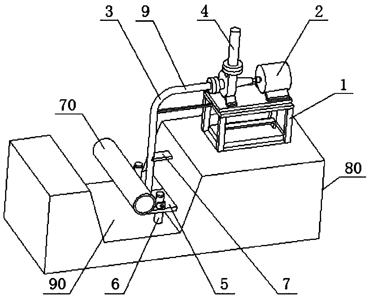
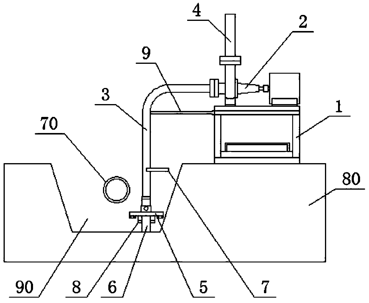
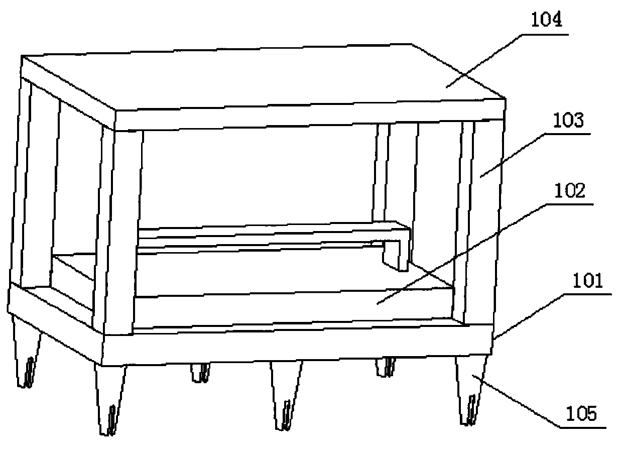
[0043] Specifically, in figure 1 , figure 2 , image 3 , Figure 4 Wherein, the number of the supporting portion 1 is one; it includes a first plate 101 for placing a counterweight 102; four pillars 103 connected to the first plate 101; a second plate 104 connected to the The column 103 is used to connect the water pump 2; and the plug 105 is connected to the first plate 101 and is used to insert the ground 80;

[0044] The insert 105 is an inverted tapered tube, and two first through grooves 105-1 are provided on the side wall; the length of the first through groove 105-1 after plane projection is that of the insert 105 after plane projection 1 / 3 of the length dimension;

[0045] The first plate 101 is a tetragonal steel plate, and a groove is left in the middle to facilitate the placement of at least one counterweight 102;

[0046] The counterweight 102 is cast and placed on the first plate 101 by a forklift, so that the supporting portion 1 can be better supported on the ground ...

Embodiment 2

[0078] Specifically, in Picture 11 Two sets of drainage devices are provided on both sides of the gas pipeline 70 to make the operation more convenient for the operator;

[0079] The working principle of the present invention: when implemented, the support 1 is set on the ground 80 to form a reliable support, so that the water pump 2 can be reliably positioned, and it has good stability during operation, and can drain the water in the excavation groove 90 , To prevent excessive water from passing through the first platform 5, affecting the operation of the operator; the first platform 5 is provided, and the position of the first platform 5 can be adjusted through the support 6, so that the operator can well control the gas pipeline 70 The position between the two is easy to operate; the second platform 7 is provided to form a ladder structure, which is convenient for operators to climb, reduces the probability of slipping, and has better safety; thereby overcoming the inconvenie...


PUM


Abstract

The invention discloses a drainage device for repairing a fuel gas pipeline. The drainage device comprises at least one supporting part, a water pump, a first platform, at least two supporting parts and at least two platforms, wherein the supporting part is arranged on the ground, the water pump is connected to the supporting part, a water inlet pipeline and a water outlet pipeline are arranged onthe water pump, and the water inlet pipeline extends into a digging groove by the water pump, the first platform is connected to the water inlet pipeline and is used for supporting an operator, the at least two supporting pieces penetrate through the first platform and are located in the first platform, and can be inserted into the digging groove and used for forming support and can be used for adjusting the position of the first platform; the at least one second platform is connected to the water inlet pipeline and facilitates the climbing of the operator. The technical problem that the operation is inconvenient after the rush repairing and excavating are conducted is overcome, and the technical effects of being convenient to operate, safe and reliable and good in repair effect are achieved, and the practicability is high.

Description

Technical field [0001] The invention relates to the technical field of equipment for emergency repairs of gas pipelines, in particular to a drainage device for emergency repairs of gas pipelines. Background technique [0002] The gas pipeline is a special pipeline for conveying combustible gas; the outdoor gas pipeline is generally buried in the ground, usually with a depth of one meter; when the gas pipeline leaks, the main valve needs to be closed to cut off the gas. Pipelines are replaced and welded, especially in the south, where there is a lot of rain and groundwater. After excavation, it is easy to cause water collection at the gas pipeline, which is very muddy. It is inconvenient for operators to stand and operate, which affects emergency repairs. effect. Summary of the invention [0003] In view of the above-mentioned shortcomings in the related art, the purpose of the present invention is to provide a drainage device for emergency repair of a gas pipeline to solve the te...

Claims


Application Information

Patent Timeline
Patent Type & Authority Applications(China)
IPC IPC(8): F16L55/16F16L55/18F04D13/06F04D29/62F04D29/046F04D29/043F04D29/00F04D29/20
CPCF04D13/06F04D29/007F04D29/043F04D29/046F04D29/20F04D29/628F16L55/16F16L55/18
Inventor 杜小军潘琦霞杜成志
Owner QUANZHOU GAS
Why Eureka
Try Eureka