
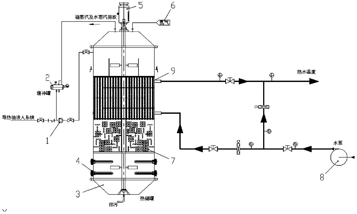
A low-valley electric heating heat transfer oil and molten salt co-storage heat supply system

A heating system and heat storage system technology, applied to heating systems and central heating, can solve problems such as difficulty in automatic control, complexity of heat conduction oil heating systems, and waste of heat

Active Publication Date: 2020-06-19
陕西圣昊朗道科技有限公司
View PDF9 Cites 0 Cited by
  • Summary
  • Abstract
  • Description
  • Claims
  • Application Information

AI Technical Summary

Problems solved by technology

[0005] (2) The complexity of the heat conduction oil heating system makes it difficult to realize automatic control when the design requirements are met
[0006] Due to the large number of equipment in the heat transfer oil heating system and unforeseen failures during operation, there are great difficulties in the automatic control of the equipment
[0007] (3) The cumbersomeness of the traditional molten salt heating system requires a large amount of equipment to meet the design requirements
[0009] (4) The start-up process of the traditional molten salt heating system is complicated
[0010] (5) In the traditional molten salt heating system, after the molten salt is melted for the first time, it cannot be solidified again, otherwise it will consume a lot of heat and melt the molten salt again, resulting in waste of heat
[0011] (6) The automation control degree of the traditional molten salt heating system is low

Method used


Image

  • A low-valley electric heating heat transfer oil and molten salt co-storage heat supply system
  • A low-valley electric heating heat transfer oil and molten salt co-storage heat supply system

Examples


Embodiment Construction

[0035] In describing the present invention, it should be understood that the terms "center", "longitudinal", "transverse", "upper", "lower", "front", "rear", "left", "right", " The orientation or positional relationship indicated by "vertical", "horizontal", "top", "bottom", "inner", "outer", "side", "end", "side" etc. is based on the Orientation or positional relationship is only for the convenience of describing the present invention and simplifying the description, and does not indicate or imply that the referred device or element must have a specific orientation, be constructed and operated in a specific orientation, and thus should not be construed as a limitation of the present invention. In addition, in the description of the present invention, unless otherwise specified, "plurality" means two or more.

[0036] In the description of the present invention, it should be noted that unless otherwise specified and limited, the terms "installation", "connection" and "connecti...


PUM


Abstract

The invention discloses a heat supply system utilizing valley electricity to heat heat conduction oil and molten salt for combined heat storage. The heat supply system utilizing the valley electricityto heat the heat conduction oil and the molten salt for combined heat storage comprises a heat conduction oil heating and heat storage system, a heat supply system body, a central processing unit anda plurality of molten salt heat storage respiration bag devices, the central processing unit is correspondingly connected with the heat supply system body and the heat conduction oil heating and heatstorage system and is used for achieving automatic control, the plurality of molten salt heat storage respiration bag devices are arranged in a heat storage tank of the heat conduction oil heating and heat storage system, and the heat supply system body is used for performing heat exchange on a heat storage medium in the heat storage tank to achieve stable control and output of an outlet workingcondition. According to the heat supply system utilizing the valley electricity to heat the heat conduction oil and the molten salt for combined heat storage, by effectively combining existing energyconfiguration problems in China, a technology of the heat storage type system in which the valley electricity and the molten salt are utilized for heat making and heat storage and heat release is performed at the peak value is developed, and peak shifting and valley filling in the aspect of electric power are completed.

Description

technical field [0001] The invention belongs to the technical field of heat supply systems, and in particular relates to a low-valley electric heating heat transfer oil and molten salt joint heat storage and heat supply system. Background technique [0002] With the development of the national economy and the continuous improvement of people's living standards, my country's energy demand structure has undergone major changes. On the one hand, there are problems such as insufficient peak power, and on the other hand, there are problems such as excessive peak-to-valley differences. The emergence of these contradictions restricts the development of the national economy. At the same time, high-temperature heat storage technology realizes the storage and release of heat energy through heat storage materials, and can also effectively solve the mismatch between energy demand and supply. However, there are still some technical difficulties in this technology, which restrict its dev...

Claims


Application Information

Patent Timeline
Patent Type & Authority Patents(China)
IPC IPC(8): F24D11/00F24D12/02F24D19/00F24D19/08F24D19/10F28D20/00F28F13/12
CPCF24D11/008F24D12/02F24D19/00F24D19/08F24D19/1084F24D19/1096F28D20/0034F28D2020/0047F28F13/12Y02B30/00Y02E60/14
Inventor 王树众王涛赵军雷杰王栋杨健乔
Owner 陕西圣昊朗道科技有限公司
Learn More