ROS-based laser radar and camera fusion calibration system and calibration method

A technology of laser radar and calibration method, which is applied in image analysis, image data processing, instruments, etc., can solve the problems of lack of information, insufficient perception dimension, etc., and achieve the effect of precise fusion, convenient embedded development and use

Active Publication Date: 2019-10-29
SOUTHEAST UNIV
View PDF3 Cites 29 Cited by
  • Summary
  • Abstract
  • Description
  • Claims
  • Application Information

AI Technical Summary

Problems solved by technology

[0005] The present invention provides a ROS-based lidar and camera fusion calibration system and calibration method, which realizes the spatial synchronization method of laser radar and camera data fusion, and solves the shortcomings of existing single sensor perception such as insufficient perception dimension and lack of information.

Method used


Image

  • ROS-based laser radar and camera fusion calibration system and calibration method
  • ROS-based laser radar and camera fusion calibration system and calibration method
  • ROS-based laser radar and camera fusion calibration system and calibration method

Examples


Embodiment 1

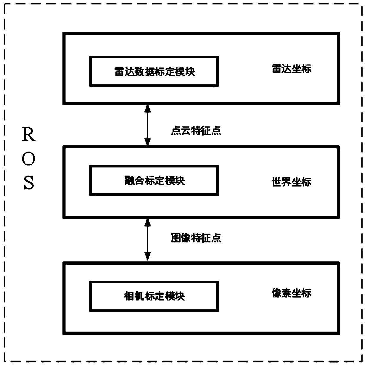
[0075] The aforementioned radar calibration module extracts a corner point of the pile barrel and 6-8 corner points of the two calibration plates through the pile barrel and two calibration plates placed at different positions outside the lidar, and obtains all the aforementioned corner points The coordinates in the world coordinate system and the coordinates in the radar coordinate system are obtained by solving the equation to obtain the transformation matrix from the radar coordinate system to the world coordinate system;

[0076] The aforementioned camera calibration module, by placing the calibration board in different angles and positions in the camera, and obtaining the internal parameters of the camera based on ROS, is to image the object in the camera coordinate system to the pixel coordinates;

[0077] The aforementioned fusion calibration module transforms the coordinates of the 7-9 corner points in the radar coordinate system in the radar calibration module to the c...

Embodiment 2

[0079] A fusion calibration method based on ROS lidar and camera, comprising the following steps:

[0080] Step 1: Obtain the internal parameters of the camera through the camera calibration module, that is, the conversion relationship from the camera coordinate system to the pixel coordinate system;

[0081] The second step: Obtain the external parameters between the lidar coordinates and the world coordinates through the radar calibration module, that is, the conversion relationship between the radar coordinate system and the world coordinate system;

[0082] Step 3: In the fusion module, obtain the 7-9 corner points of the pile bucket in the radar calibration module and the two calibration plates as feature points, select 9 feature points, and obtain the aforementioned 9 feature points in the world coordinates respectively coordinate system, pixel coordinate system;

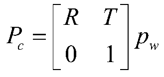
[0083] Step 4: Solve the pose estimation problem through the fusion calibration module, that is, solve the...


PUM


Abstract

The invention relates to an ROS-based laser radar and camera fusion calibration system and calibration method, and the system comprises: a radar calibration module which is used for obtaining the external parameters of a laser radar, i.e., the conversion relation from a radar coordinate system of the laser radar to a world coordinate system; a camera calibration module which is used for acquiringinternal parameters of the camera; a fusion calibration module which is used for receiving the external parameters of the laser radar and the internal parameters of the camera and solving the externalparameters of the camera, namely solving a transformation relation from a world coordinate system to a camera coordinate system. Data transmission among the radar calibration module, the camera calibration module and the fusion calibration module is realized based on an ROS platform. the radar calibration module comprises a laser radar, a pile barrel and two calibration plates, and the camera calibration module comprises a camera and a calibration plate. According to the space synchronization method for realizing data fusion of the laser radar and the camera, the defects of insufficient sensing dimension, lack of information and the like existing in the conventional single sensor sensing are overcome.

Description

technical field [0001] The invention relates to a fusion calibration system and calibration method of a laser radar and a camera based on ROS, and belongs to the technical field of fusion between a laser radar and a camera. Background technique [0002] The environmental perception technology of unmanned vehicles mainly uses external sensors, such as laser radar, camera, millimeter wave radar, etc. to detect the surrounding environment, so as to ensure that unmanned vehicles can timely and accurately perceive the safety hazards existing in the road environment. Take quick steps to avoid traffic accidents. Environmental perception is equivalent to the eyes of unmanned vehicles, and plays an irreplaceable role in ensuring the safe driving of unmanned vehicles. [0003] At present, there are many methods of environmental perception: visual sensing is based on machine vision to obtain image information of the surrounding environment of the vehicle, and perceive the surrounding ...

Claims


Application Information

Patent Timeline
Patent Type & Authority Applications(China)
IPC IPC(8): G06T7/80
CPCG06T7/85Y02A90/10
Inventor 殷国栋薛培林刘帅鹏吴愿耿可可庄伟超黄文涵
Owner SOUTHEAST UNIV
Why Eureka
Try Eureka