Mobile robot map construction method based on visual inertial navigation fusion and related equipment

A mobile robot and map construction technology, applied in the field of mobile robot map construction based on visual inertial navigation fusion, can solve the problems of inaccurate fusion of camera and IMU data, real-time error of back-end processing, low information efficiency, etc., to shorten the initialization. time, improve robustness, and solve the effect of poor real-time performance

Active Publication Date: 2021-07-09
ANHUI UNIVERSITY OF TECHNOLOGY AND SCIENCE
View PDF8 Cites 10 Cited by
  • Summary
  • Abstract
  • Description
  • Claims
  • Application Information

AI Technical Summary

Problems solved by technology

[0005] The purpose of the present invention is to provide a mobile robot map construction method based on visual inertial navigation fusion, to solve the inability to accurately fuse camera and IMU data in the prior art, resulting in low efficiency, large errors, and back-end processing errors in reading current map point pose information Technical problems with poor real-time performance

Method used


Image

  • Mobile robot map construction method based on visual inertial navigation fusion and related equipment
  • Mobile robot map construction method based on visual inertial navigation fusion and related equipment
  • Mobile robot map construction method based on visual inertial navigation fusion and related equipment

Examples


Embodiment 1

[0047] The invention provides a mobile robot map construction method based on visual inertial navigation fusion, and a system using the method includes a simulated visual system and a simulated inertial system at the same time.

[0048] The analog vision system includes: two visual perception standardizers, signal conditioning circuit, analog-to-digital (AD) converter. Wherein, the two visual markers are arranged symmetrically, and the main control chip is preferably an STM32 main control chip.

[0049] Analog inertial systems include: gyroscopes, accelerometers, signal conditioning circuits, and analog-to-analog (AD) converters. Among them, the inertial measurement unit chooses the highly integrated MPU6050 chip, which contains a three-axis gyroscope, a three-axis accelerometer and a three-axis magnetometer.

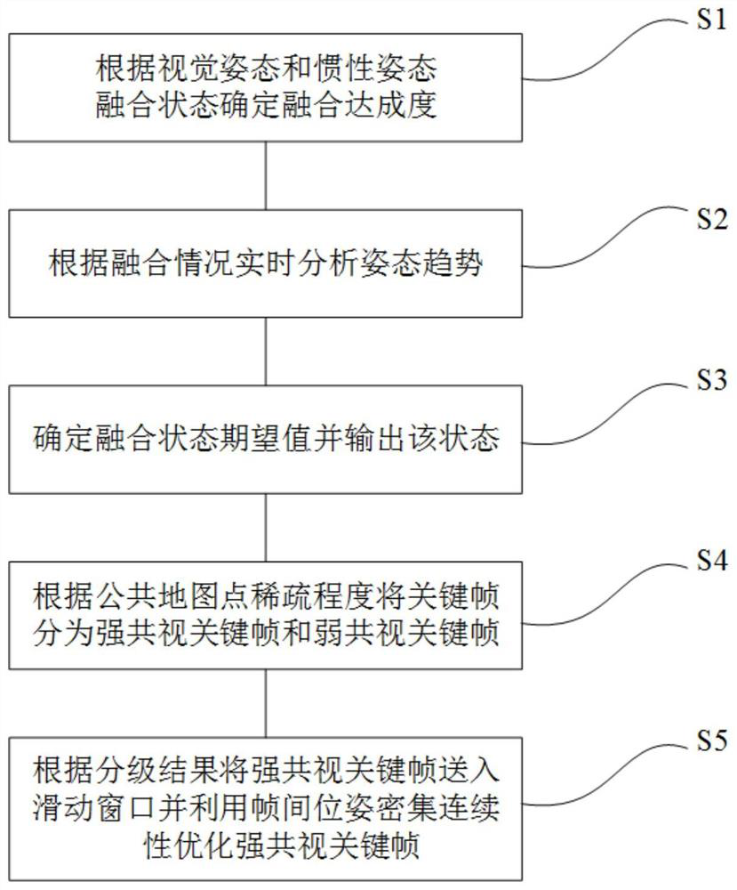
[0050] Such as Figure 1-3 As shown, the method specifically includes;

[0051] Step S1, determine the degree of fusion achievement according to the fusion state of ...

Embodiment 2

[0110] Corresponding to Embodiment 1 of the present invention, Embodiment 2 of the present invention provides a computer-readable storage medium on which a computer program is stored. When the program is executed by a processor, the following steps are implemented according to the method of Embodiment 1:

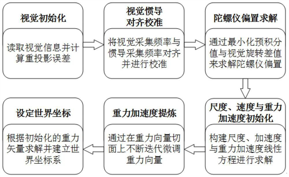
[0111]Step S1, determine the degree of fusion achievement according to the fusion state of visual attitude and inertial attitude, and complete visual initialization, visual-inertial calibration and alignment, and inertial initialization.

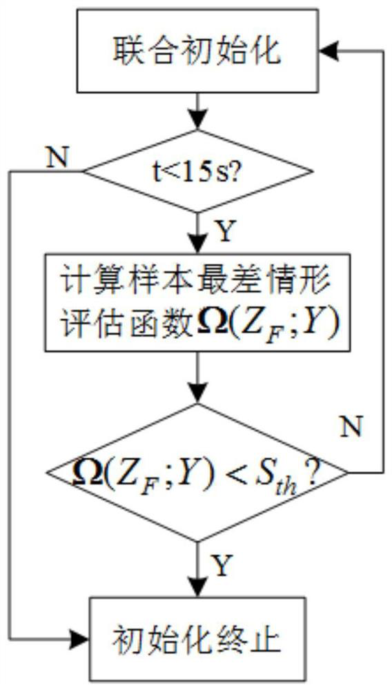
[0112] Step S2, constructing a situation evaluation function to analyze posture trends in real time.

[0113] Step S3, determine the local expected value of the fusion state and output the state.

[0114] In step S4, the key frames are divided into strong common view key frames and weak common view key frames according to the degree of sparsity of common map points.

[0115] Step S5, send the strong common-view keyframes into the sliding ...

Embodiment 3

[0119] Corresponding to Embodiment 1 of the present invention, Embodiment 3 of the present invention provides a computer device, including a memory, a processor, and a computer program stored in the memory and operable on the processor. When the processor executes the program, the The following steps:

[0120] Step S1, determine the degree of fusion achievement according to the fusion state of visual attitude and inertial attitude, and complete visual initialization, visual-inertial calibration and alignment, and inertial initialization.

[0121] Step S2, constructing a situation evaluation function to analyze posture trends in real time.

[0122] Step S3, determine the local expected value of the fusion state and output the state.


PUM


Abstract

The invention discloses a mobile robot map construction method based on visual inertial navigation fusion and related equipment, and the method comprises the steps: S1, determining a fusion achievement degree according to a visual attitude and inertial attitude fusion state, and completing visual initialization, visual inertial calibration alignment and inertial initialization; s2, constructing a situation evaluation function to analyze a posture trend in real time; s3, determining a fusion state local expected value and outputting the state; s4, dividing the key frame into a strong common-view key frame and a weak common-view key frame according to the point sparse degree of the public map; and S5, sending the strong common-view key frame into a sliding window according to a grading result, optimizing the strong common-view key frame by utilizing inter-frame pose dense continuity, and drawing and correcting the self-sensing map by virtue of a relation of observation map points. Accurate fusion between the camera data and the IMU data is guaranteed, and the system is high in efficiency of reading the current map point pose information and small in error.

Description

technical field [0001] The invention belongs to the technical field of simultaneous positioning and map creation (Simultaneous Location And Mapping, SLAM), and relates to a mobile robot map construction method based on visual inertial navigation fusion and related equipment. Background technique [0002] The core problem of simultaneous positioning and map creation (Simultaneous Location And Mapping, SLAM) is that the robot is required to first explore the environment in an unfamiliar environment to understand the environment (build a map), and use the map to track the position of the robot in the environment simultaneously. (position). Traditional solutions to SLAM problems are mainly based on mathematical probability methods, among which Kalman filter, particle filter and maximum expectation algorithm are the basic solutions to robot SLAM problems. Although these traditional SLAM algorithms still use laser ranging and sonar ranging to collect information, the information ...

Claims


Application Information

Patent Timeline
Patent Type & Authority Applications(China)
IPC IPC(8): G01C21/16G01C21/20G06F17/15G06F17/16
CPCG01C21/20G01C21/005G01C21/165G06F17/15G06F17/16
Inventor 陈孟元郭俊阳陈何宝
Owner ANHUI UNIVERSITY OF TECHNOLOGY AND SCIENCE
Why Eureka
Try Eureka