
Broadband side directional ceiling antenna

A ceiling-mounted antenna and broadband technology, applied in antennas, antenna parts, antenna supports/installation devices, etc., can solve problems such as wire binding, poor sealing of connection structures, affecting maintenance efficiency, etc., to ensure waterproof and moisture-proof. Performance, stable limit, good protection effect

Active Publication Date: 2019-10-29
GUILIN UNIV OF ELECTRONIC TECH
View PDF12 Cites 0 Cited by
  • Summary
  • Abstract
  • Description
  • Claims
  • Application Information

AI Technical Summary

Problems solved by technology

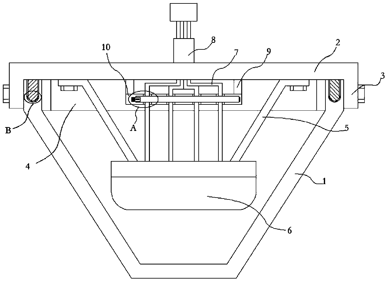
[0005] The purpose of the present invention is to solve the problem that most of the connection between the ceiling antenna cover and the cover plate in the prior art is fixed by a single bolt. Moisture-proof performance, and the current antenna body is connected with many different wires. Most of the wires are directly bound together at present, which brings inconvenience to the staff when maintenance and inspection are required, and affects the maintenance efficiency. A proposed A Broadband Side Directional Ceiling Antenna

Method used


Image

  • Broadband side directional ceiling antenna
  • Broadband side directional ceiling antenna
  • Broadband side directional ceiling antenna

Examples


Embodiment Construction

[0020] The following will clearly and completely describe the technical solutions in the embodiments of the present invention with reference to the accompanying drawings in the embodiments of the present invention. Obviously, the described embodiments are only some, not all, embodiments of the present invention.

[0021] In describing the present invention, it should be understood that the terms "upper", "lower", "front", "rear", "left", "right", "top", "bottom", "inner", " The orientation or positional relationship indicated by "outside", etc. is based on the orientation or positional relationship shown in the drawings, and is only for the convenience of describing the present invention and simplifying the description, rather than indicating or implying that the referred device or element must have a specific orientation, so as to Specific orientation configurations and operations, therefore, are not to be construed as limitations on the invention.

[0022] refer to Figure ...


PUM


Abstract

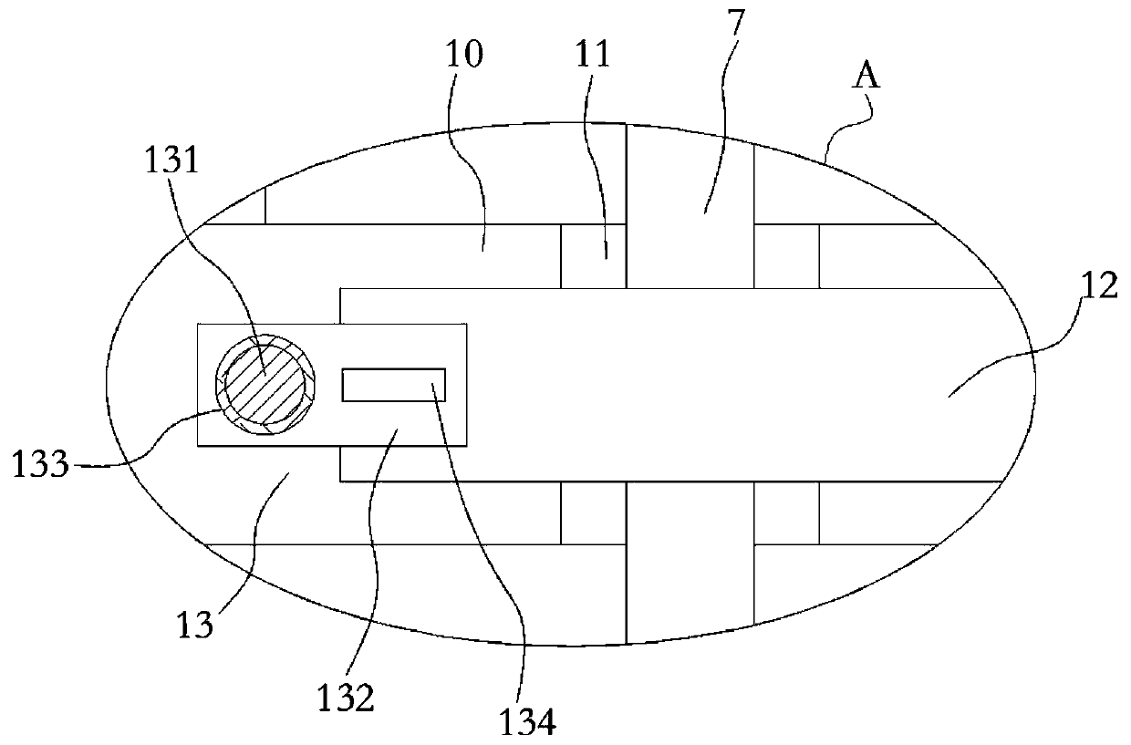
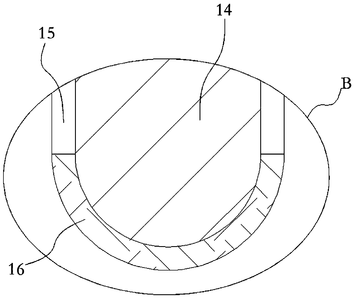
The invention relates to the field of the communication technology, and discloses a broadband side directional ceiling antenna. The broadband side directional ceiling antenna comprises a cover shell.The upper end of the cover shell is fixedly connected with a cover plate, and the outer wall of the cover plate is fixedly connected with a positioning ring plate sleeving the outer portion of the cover shell. The lower end of the cover plate is fixedly connected with a threaded ring with threads on the outer wall, and the inner wall of the upper end of the cover shell is provided with internal threads matchingly connected with the threaded ring, and the lower end of the cover plate is fixedly connected with an antenna body through a bracket, and the antenna body is connected with many connection lines, the upper end of the cover plate is fixedly connected with a fixing cylinder, the upper ends of the connection lines are all extended out of the cover plate and extended into the fixing cylinder, the lower end of the cover plate is fixedly connected with two symmetrically arranged vertical plates, the lower ends of the two vertical plates are fixedly connected with the same line fixingplate. The broadband side directional ceiling antenna effectively ensures the waterproof and moisture-proof performances of the connecting mechanism between the cover plate and the cover shell, and the connection lines can be separately put, and therefore, the problem is avoided that the plurality of connection lines are entangled with each other to affect the post-inspection and maintenance.

Description

technical field [0001] The invention relates to the field of communication technology, in particular to a broadband-side directional ceiling antenna. Background technique [0002] The indoor ceiling antenna is a kind of mobile communication system antenna, which is mainly used for indoor signal coverage. In the 3G era, indoor voice, data, and high-speed multimedia services are densely distributed, and the indoor distribution system will play an important role in the construction and optimization of 3G networks. [0003] At present, indoor coverage systems and wireless local area networks are important components of modern mobile communication systems, and broadband ceiling antennas are indispensable devices. Just like the light bulbs used in lighting systems, future intelligent business buildings, exhibition venues, and even high-end residential buildings will need to install ceiling antennas. [0004] The connection between the current ceiling antenna cover and the cover ...

Claims


Application Information

Patent Timeline
Patent Type & Authority Applications(China)
IPC IPC(8): H01Q1/42H01Q1/12H01Q1/00F16J15/10
CPCF16J15/10H01Q1/00H01Q1/007H01Q1/1221H01Q1/42
Inventor 黄沁鹏其他发明人请求不公开姓名
Owner GUILIN UNIV OF ELECTRONIC TECH
Learn More