
Electrical connector

An electrical connector and butt slot technology, which is applied in the direction of connection, two-part connection device, and parts of the connection device, can solve the problems of increasing the volume of the connector, breaking the side plate, increasing the thickness of the insulating body, etc. The effect of miniaturization and volume reduction

Active Publication Date: 2019-10-29
FUDING PRECISION COMPONENTS SHENZHEN +1
View PDF3 Cites 5 Cited by
  • Summary
  • Abstract
  • Description
  • Claims
  • Application Information

AI Technical Summary

Problems solved by technology

[0003] However, the protrusion structure can only temporarily protect the insulating body when the tongue plate of the docking connector is inserted into the opening, and will still contact the insulating body when the tongue plate of the docking connector enters the opening and moves in the docking cavity. The side plate will be touched and cause scratches to the side plate. In severe cases, the side plate will also have the risk of breaking
In addition, since the outer surfaces of the side panels on the left and right sides of the insulating body need to be further provided with lugs that are further protruded from the side walls of the metal shell to snap fit each other, this will also increase the distance between the left and right sides of the insulating body. Thickness, and further increases the volume of the connector, is not conducive to miniaturization

Method used


Image

  • Electrical connector
  • Electrical connector
  • Electrical connector

Examples


Embodiment Construction

[0026] In order to facilitate a better understanding of the purpose, structure, features, and effects of the present invention, the present invention will now be further described in conjunction with the accompanying drawings and specific embodiments.

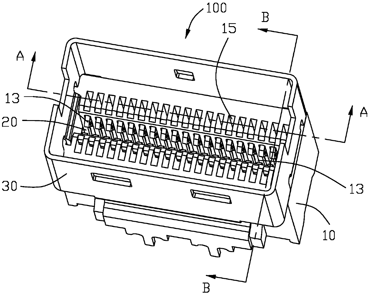
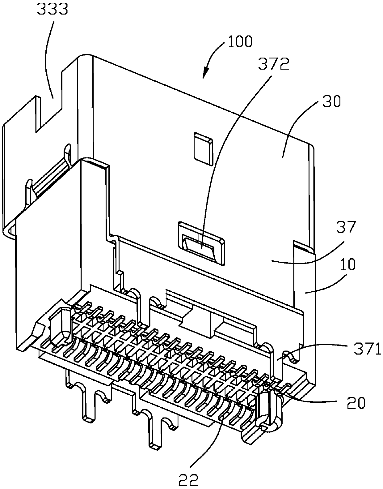
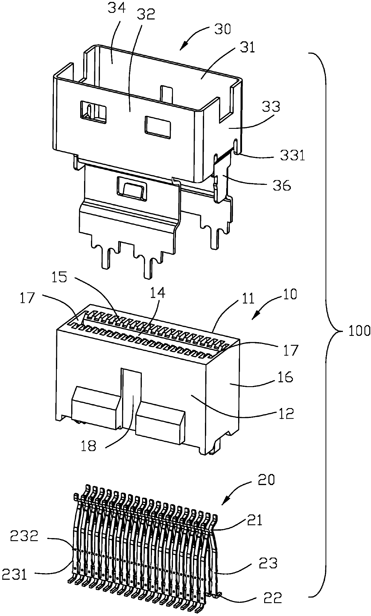
[0027] see Figure 1-4 As shown, the preferred embodiment of the electrical connector 100 of the present invention is a SFF8654 or SlimSAS socket connector, and the connector 100 is used to be mounted on a circuit board (not shown) and mated with a mating connector (not shown) electrical connection. In this embodiment, the electrical connector 100 is arranged in the vertical direction, and includes an insulating body 10 extending in the vertical direction, a plurality of conductive terminals 20 disposed on the insulating body 10 to be electrically connected to the mating connector, and Metal shell 30. In other embodiments, the electrical connector 100 may also be arranged in a right angle manner, that is, the insulating body ...


PUM


Abstract

The invention discloses an electrical connector. The electrical connector includes an insulation body, multiple conductive terminals and a metal shell; the insulation body includes a first plate part,a second plate part and docking grooves; the docking grooves are located between the first plate part and the second plate part and form openings penetrating outward on one end of the insulation body; the first plate part and the second plate part are provided with multiple terminal grooves; the conductive terminals are provided with contact parts and tail parts; the metal shell includes a firstwall, a pair of sidewalls extending from the two sides of the first wall, and an accommodating chamber; the insulation body is provided with a pair of inserting grooves; the two sidewalls of the metalshell are respectively provided with guiding parts and reinforcement parts; and the two reinforcement parts are accommodated in the corresponding inserting grooves and enclosed to form the docking grooves with the first plate part and the second plate part, so that a docking connector can be prevented from damaging the insulation body when entering the openings and after entering the docking grooves.

Description

【Technical field】 [0001] The invention relates to an electrical connector, in particular to an electrical connector which can be installed on a circuit board. 【Background technique】 [0002] For related prior art, please refer to an electronic connector disclosed in Chinese Utility Model Patent No. CN205693075U. The electronic connector is used to be installed on a circuit board and includes an insulating body, a plurality of conductive terminals and a shielding shell. The insulating body includes a docking cavity formed by a first plate portion, a second plate portion, and two side plate portions, and the opposite surfaces of the first plate portion and the second plate portion are provided with a plurality of a terminal slot; each of the conductive terminals has a contact portion arranged in the terminal slot and a tail portion extending out of the insulating body; the shielding shell is fixed at the opening end of the docking cavity of the insulating body, The shielding ...

Claims


Application Information

Patent Timeline
Patent Type & Authority Applications(China)
IPC IPC(8): H01R12/71H01R13/502H01R13/631
CPCH01R12/716H01R13/502H01R13/631H01R13/6581H01R13/6594H01R24/60
Inventor 陈德金刘兴良
Owner FUDING PRECISION COMPONENTS SHENZHEN
Learn More