Supercharge Your Innovation With Domain-Expert AI Agents!

Communication machine room inspection system

A communication room and through-slot technology, which is applied in the parts of the TV system, image communication, TV, etc., can solve the problems of inconvenient inspection information recording and viewing, inability to realize remote real-time monitoring, lack of flexibility, etc., and reduce human resources. Output, easy to patrol, the effect of a wide range of patrols

Active Publication Date: 2019-10-29
浙江省邮电工程建设有限公司
View PDF6 Cites 8 Cited by
  • Summary
  • Abstract
  • Description
  • Claims
  • Application Information

AI Technical Summary

Problems solved by technology

[0002] With the continuous development of society, communication has become a feature of this century. Almost all large and medium-sized enterprises have their own dedicated communication equipment and communication room. However, the communication room has strict temperature and humidity control. The traditional information Most of the environmental detection systems in the computer room can only detect temperature, humidity, smoke, etc., and send an alarm signal when the temperature and humidity exceed the set value, or directly turn on the fire protection system after detecting smoke, which is relatively rigid and lacks flexibility. Even if the installed video monitor , and can only be used as video data for checking the cause of the accident after the accident, and cannot realize remote real-time monitoring
[0003] Most of the records after inspections in the communication room are in the form of paper forms. As time goes by, due to the increase in inspection records and information accumulation, it is not convenient to record and view inspection information.

Method used


Image

  • Communication machine room inspection system
  • Communication machine room inspection system
  • Communication machine room inspection system

Examples


Embodiment Construction

[0028] In order to make the purpose, features and advantages of the present invention more obvious and understandable, the technical solutions in the embodiments of the present invention will be clearly and completely described below in conjunction with the accompanying drawings in the embodiments of the present invention. Obviously, the following The described embodiments are only some, not all, embodiments of the present invention. Based on the embodiments of the present invention, all other embodiments obtained by persons of ordinary skill in the art without making creative efforts belong to the protection scope of the present invention.

[0029] The technical solutions of the present invention will be further described below in conjunction with the accompanying drawings and through specific implementation methods.

[0030] In the description of the present invention, it should be understood that the orientations or positional relationships indicated by the terms "upper", "...


PUM


Abstract

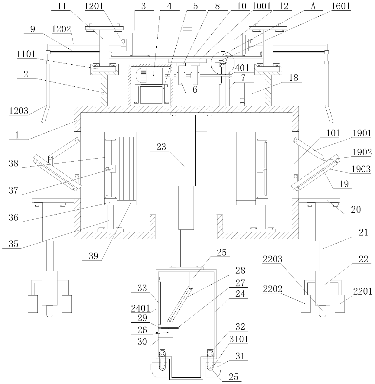
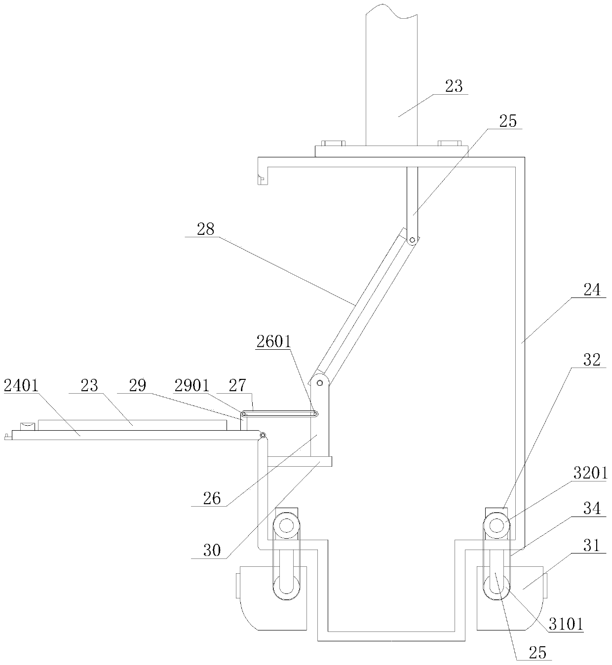
The invention discloses a communication machine room inspection system including a walking shell, a rectangular through groove, a support and a dustproof shell, a travelling motor, a motor main shaft,a motor mounting rack, a travelling gear, a bearing bracket and a meshing rack, a pipe frame and a bearing plate, a mounting plate and a guide rail plate, a guide rail batten, a liquid storage bottleand an infusion port, an infusion tube and a gas nozzle, a steering rack, a driven bevel gear, a driving bevel gear, a connecting shaft and a steering gear, a connecting frame and an oil cylinder, anLED lamp panel, a long rod and a short rod, an LED lamp tube, a transverse plate and an electric push rod, an installation column, a temperature and humidity sensor, a dust detector, a smoke alarm, ahydraulic push rod, an inspection box, a cover plate, an upper fixing frame, a lower fixing frame, first limiting columns, connecting rods, a display screen, vertical rods, second limiting columns, atransverse partition plate, a DC camera, a driven belt wheel, a steering engine, a driving belt wheel, a keyboard, a transmission belt, a fan frame, a fan shell, fan motors, exhaust impellers, filters and fan-shaped plates. The inspection tour range is wide, and inspection tour is convenient to carry out.

Description

technical field [0001] The invention relates to a patrol system, in particular to a communication machine room patrol system, which belongs to the technical field of communication machine room patrol application. Background technique [0002] With the continuous development of society, communication has become a feature of this century. Almost all large and medium-sized enterprises have their own dedicated communication equipment and communication room. However, the communication room has strict temperature and humidity control. The traditional information Most of the environmental detection systems in the computer room can only detect temperature, humidity, smoke, etc., and send an alarm signal when the temperature and humidity exceed the set value, or directly turn on the fire protection system after detecting smoke, which is relatively rigid and lacks flexibility. Even if the installed video monitor , and can only be used as video data for checking the cause of the accide...

Claims


Application Information

Patent Timeline
IPC IPC(8): H04N5/225G08B17/10F16M11/04F16M11/10F16M11/18F16M11/28F16M11/42
CPCG08B17/10F16M11/04F16M11/10F16M11/18F16M11/28F16M11/425H04N23/56H04N23/45
Inventor 沈察明孙雪琳雷巧丽黄梦阳
Owner 浙江省邮电工程建设有限公司
Features
  • R&D
  • Intellectual Property
  • Life Sciences
  • Materials
  • Tech Scout
  • Unparalleled Data Quality
  • Higher Quality Content
  • 60% Fewer Hallucinations
Learn More