
Electronic equipment

A technology for electronic equipment and protective cover plate, applied in the field of electronic equipment, can solve problems such as unfavorable thin design of electronic equipment, large volume of camera module, etc., and achieve the effect of rationalizing the overall structure and layout, reducing material costs, and reducing assembly costs.

Inactive Publication Date: 2019-10-29
GUANGDONG OPPO MOBILE TELECOMM CORP LTD
View PDF8 Cites 2 Cited by
  • Summary
  • Abstract
  • Description
  • Claims
  • Application Information

AI Technical Summary

Problems solved by technology

[0002] In related technologies, the overall volume of the camera module is large, and when the camera module is applied to electronic equipment, it is not conducive to the thin and light design of electronic equipment

Method used


Image

  • Electronic equipment
  • Electronic equipment
  • Electronic equipment

Examples


Embodiment Construction

[0026] The following describes in detail the embodiments of the present application, examples of which are illustrated in the accompanying drawings, wherein the same or similar reference numerals refer to the same or similar elements or elements having the same or similar functions throughout. The embodiments described below with reference to the accompanying drawings are exemplary and are only used to explain the present application, but should not be construed as a limitation on the present application.

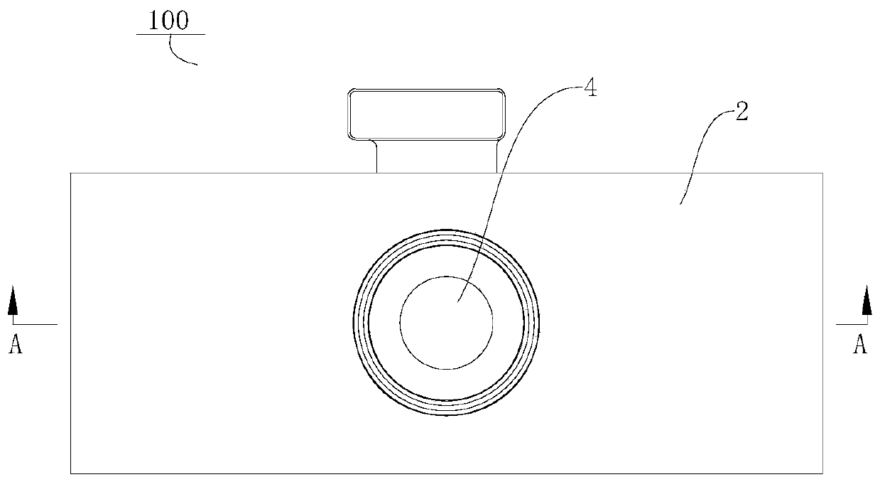
[0027] The electronic device 100 according to the embodiment of the present application is described below with reference to the accompanying drawings.

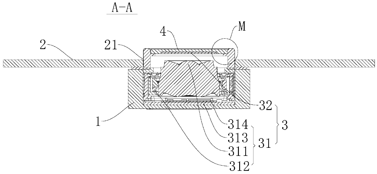
[0028] refer to Figure 1-Figure 2 As shown, the electronic device 100 according to the embodiment of the present application includes a front case 1 , a cover body 2 and a camera module 3 .

[0029] Specifically, the cover body 2 is provided on the front case 1 , and a camera hole 21 is formed on the cover body 2 . Spec...


PUM


Abstract

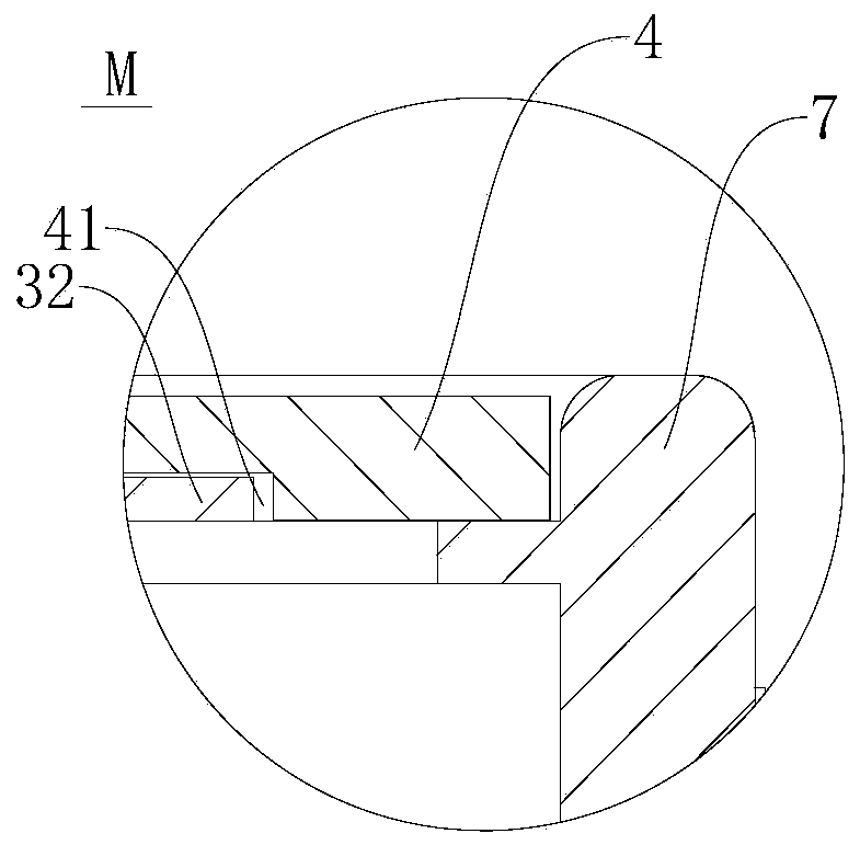
The invention discloses electronic equipment. The electronic equipment comprises a front shell; a cover body which is arranged on the front shell, wherein a camera hole is formed in the cover body; acamera module which comprises a camera main body and an optical filter, wherein the camera main body is installed on the front shell, a lens of the camera main body is right opposite to the camera hole, the optical filter and the camera main body are arranged in a split mode, and the optical filter is arranged at the camera hole. According to the electronic equipment, the optical filter is independent from the camera main body and is externally arranged at the camera hole, and in this way, the arrangement of an optical filter bracket in the camera main body can be cancelled; the material costand the assembly cost are reduced, the thickness of the camera main body is reduced, the optical filter is arranged at the camera hole, the installation space at the camera hole is fully utilized, theoverall structural layout of the electronic equipment is more reasonable, and the light and thin design of the electronic equipment is realized.

Description

technical field [0001] The present application relates to the technical field of electronic devices, and in particular, to an electronic device. Background technique [0002] In the related art, the overall volume of the camera module is relatively large, and when the camera module is applied to an electronic device, it is not conducive to the light and thin design of the electronic device. SUMMARY OF THE INVENTION [0003] One purpose of the present application is to propose an electronic device, in which the filter of the camera module is externally placed and arranged on the cover body, the volume of the camera body is reduced, and the light and thin design of the electronic device is facilitated. [0004] An electronic device according to an embodiment of the present application includes: a front case; a cover body, the cover body is provided on the front case, and a camera hole is formed on the cover body; a camera module, the camera module includes a camera A main b...

Claims


Application Information

Patent Timeline
IPC IPC(8): H04N5/225H04M1/02
CPCH04M1/0264H04N23/54H04N23/00H04N23/57H04N23/55
Inventor 贾玉虎
Owner GUANGDONG OPPO MOBILE TELECOMM CORP LTD
Learn More