Cooling liquid pot installation structure, cooling liquid pot and installation support frame

A technology of mounting structure and mounting bracket, applied in the direction of engine cooling, engine components, machine/engine, etc., can solve the problem of strict requirements of engine cooling system, and achieve the optimization of the installation process, shorten the installation time, and reduce the installation space. Effect

Inactive Publication Date: 2020-01-10
SAIC GENERAL MOTORS +1
View PDF6 Cites 0 Cited by
  • Summary
  • Abstract
  • Description
  • Claims
  • Application Information

AI Technical Summary

Problems solved by technology

[0002] With the requirements of energy saving and emission reduction, the traditional naturally aspirated engine can no longer meet the requirements, the application of more efficient turbocharged engines is gradually increasing, and the requirements for the engine cooling system are be

Method used


Image

  • Cooling liquid pot installation structure, cooling liquid pot and installation support frame
  • Cooling liquid pot installation structure, cooling liquid pot and installation support frame
  • Cooling liquid pot installation structure, cooling liquid pot and installation support frame

Examples


Example Embodiment

[0021] It is easy to understand that, according to the technical solution of the present invention, without changing the essential spirit of the present invention, a person of ordinary skill in the art can propose a variety of alternative structural modes and implementation modes. Therefore, the following specific embodiments and drawings are only exemplary descriptions of the technical solutions of the present invention, and should not be regarded as all of the present invention or as a limitation or limitation to the technical solutions of the present invention.

[0022] In the following description, various parameters and components are described for embodiments of different configurations, and these specific parameters and components are only examples and do not limit the embodiments of the present application.

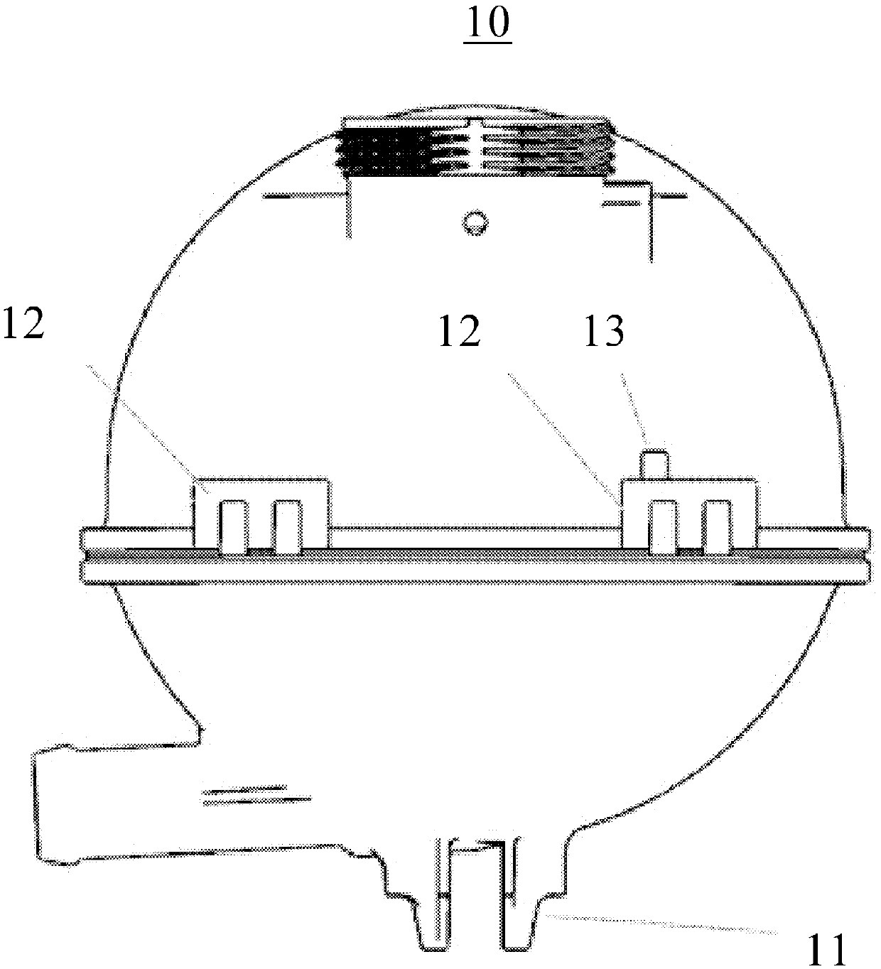
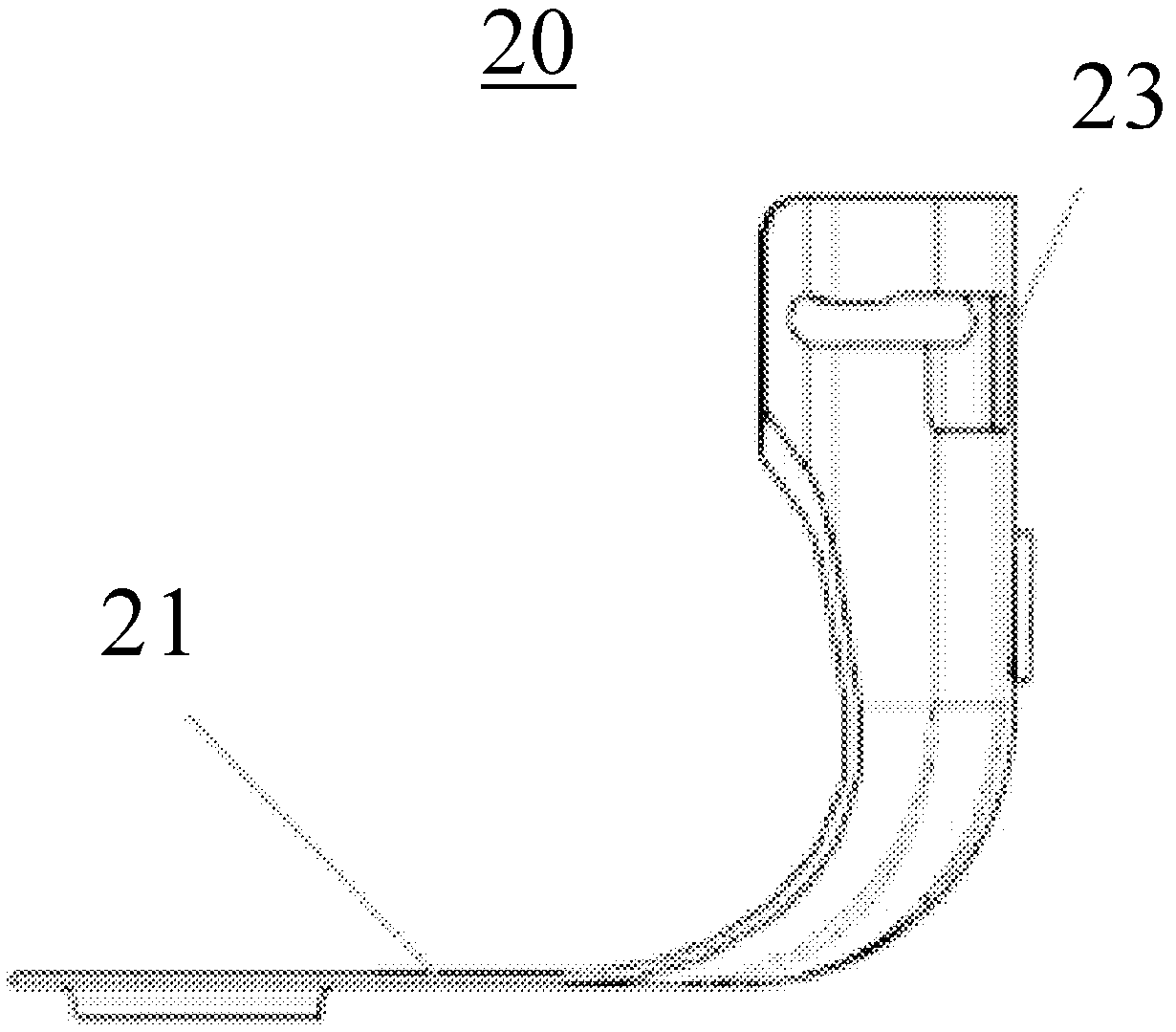
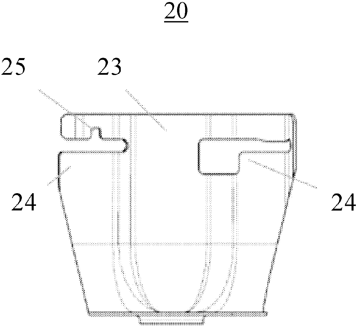
[0023] According to an embodiment of the present invention combined figure 1 , 2 , 3, 4, and 5 are shown, where it can be seen that the cooling liquid pot installation ...


PUM


Abstract

The invention discloses a cooling liquid pot installation structure, a cooling liquid pot and an installation support frame. The cooling liquid pot installation structure comprises the cooling liquidpot and the installation support frame used for the cooling liquid pot. The cooling liquid pot comprises a support seat, an installation tooth part and a boss. The installation support frame comprisesa support face, a support hole in the support face, a pre-locating face, an installation face and a groove. The support face is used for bearing the cooling liquid pot. The support hole is used for fixing the support seat of the cooling liquid pot. The pre-locating face is used for pre-locating of the cooling liquid pot. The installation face is used for being matched with the installation toothpart of the cooling liquid pot so as to limit the cooling liquid pot. The groove is used for being matched with the boss of the cooling liquid pot so as to limit the cooling liquid pot. According to the cooling liquid pot installation structure, the installation space can be reduced, and the installation process is optimized.

Description

technical field [0001] The invention relates to the field of automobiles, in particular to a cooling liquid pot installation structure, a cooling liquid pot and a mounting bracket. Background technique [0002] With the requirements of energy saving and emission reduction, traditional naturally aspirated engines can no longer meet the requirements, and the application of more efficient turbocharged engines is gradually increasing, and the requirements for engine cooling systems are becoming increasingly stringent. At the same time, the space layout of the front cabin has always been facing great challenges. How to arrange all the parts in a limited space and how to make the installation space of the parts more effective has always been a problem for designers to think about. Contents of the invention [0003] The present invention proposes a coolant pot installation structure, which can reduce the installation space and optimize the installation process. [0004] Accordin...

Claims


Application Information

Patent Timeline
IPC IPC(8): F01P11/00
CPCF01P11/00F01P2050/22
Inventor 王倩赵自敬张鑫
Owner SAIC GENERAL MOTORS
Why Eureka
Try Eureka