Automatic assembling screw device

An automatic combination and screw technology, applied in metal processing, metal processing equipment, manufacturing tools, etc., can solve the problem of not being able to remind the staff of the whereabouts of materials in time, increase the labor intensity of the staff, and reduce the overall practicability of the device, and achieve the effect. Accurate, labor-intensive, and time-wasted effects

Active Publication Date: 2019-11-01
浙江天工紧固件股份有限公司
View PDF7 Cites 3 Cited by
  • Summary
  • Abstract
  • Description
  • Claims
  • Application Information

AI Technical Summary

Problems solved by technology

[0004] The purpose of the present invention is to provide an automatic combination screw device to solve the above-mentioned background technology that the current screw combination device cannot ensure that there is sufficient material inside the tray, the feeding cycle is short, and the labor intensity of the staff is increased. At the same time, there is no detection device during the screw discharge process, and unqualified screws are easy to flow into the production line, and the existing material detection device can only detect screws of specified specifications, which has low flexibility and has no alarm function. It is impossible to remind the staff of the whereabouts of the materials in time, which reduces the overall practicability of the device

Method used


Image

  • Automatic assembling screw device
  • Automatic assembling screw device
  • Automatic assembling screw device

Examples


Embodiment Construction

[0028] The following will clearly and completely describe the technical solutions in the embodiments of the present invention with reference to the accompanying drawings in the embodiments of the present invention. Obviously, the described embodiments are only some, not all, embodiments of the present invention. Based on the embodiments of the present invention, all other embodiments obtained by persons of ordinary skill in the art without making creative efforts belong to the protection scope of the present invention.

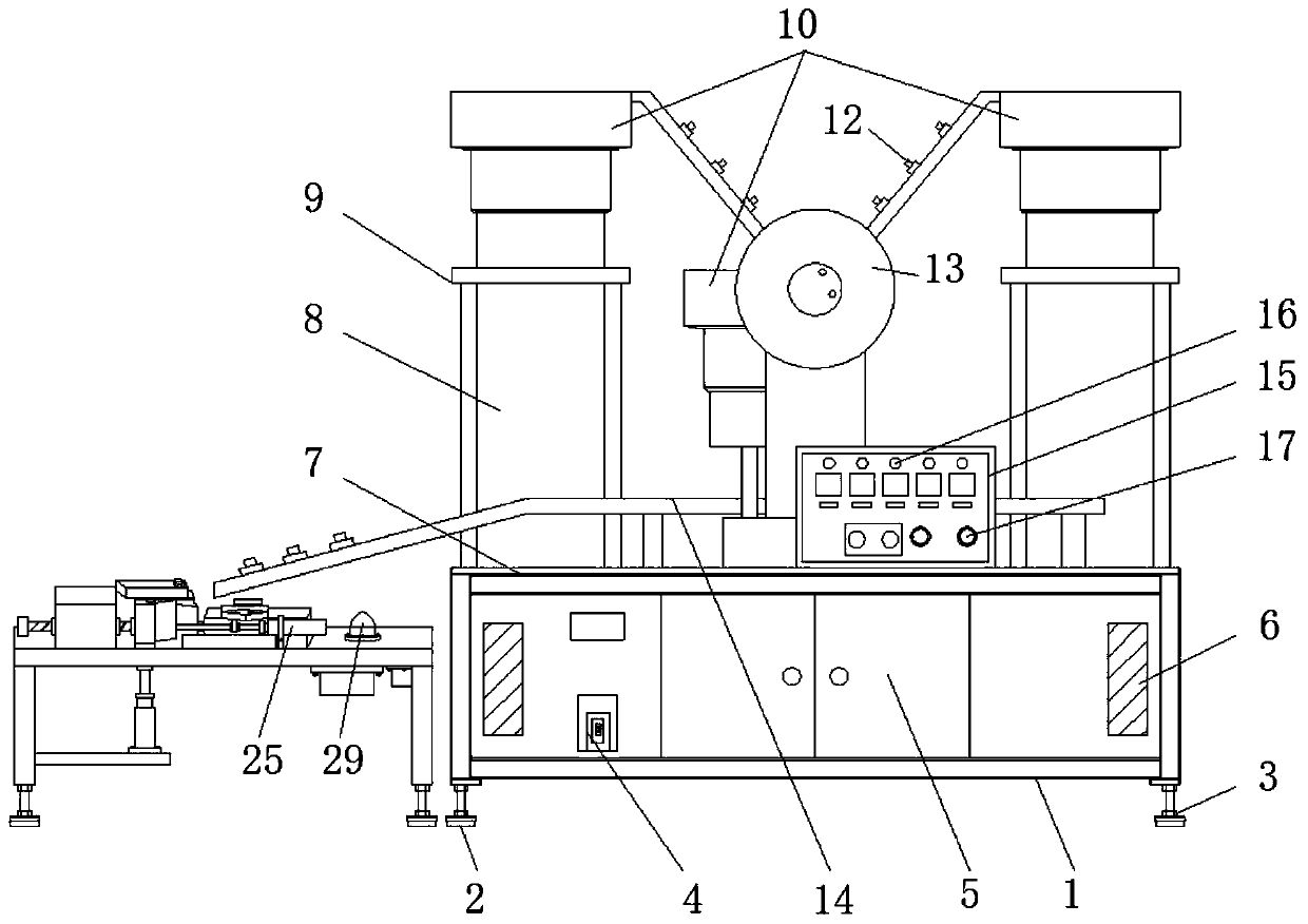
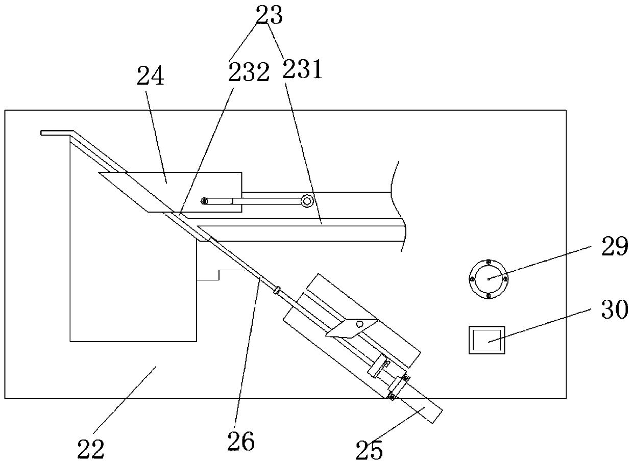
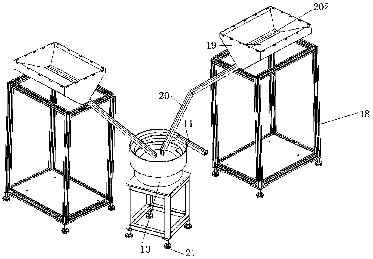
[0029] see Figure 1-9 , the present invention provides a technical solution: an automatic combination screw device, including an equipment rack 1, an adjustable foot 2 is movably installed at the lower end of the equipment rack 1, and the connection between the adjustable foot 2 and the equipment rack 1 An adjusting screw 3 is installed in the center, a power switch 4 is installed on the left side of the lower end of the equipment rack 1, a maintenance door 5...


PUM


Abstract

The invention discloses an automatic assembling screw device. The automatic assembling screw device comprises a equipment rack, wherein adjustable supporting legs are movably installed at the lower end of the equipment rack, adjusting screws are movably installed between the adjustable supporting legs and the equipment rack, a power switch is movably installed on the left side of the lower end ofthe equipment rack, a vibrating material falling plate is fixedly installed at the upper end of an installing base, and an assembling table is fixedly installed at the lower end of the vibrating material falling plate. According to the automatic assembling screw device, large vibrating plates which are symmetrically arranged are used as vibration feeding plates to supply screw parts, so that the screw parts inside the vibration feeding plates are kept in a sufficient state; material discharging is detected through a photoelectric sensor, operators worker is reminded that the equipment occurs abnormity, so that the workload of the operators can be reduced; an electrical signal loop is formed by two electrodes and the screws, so that an alarm effect can be achieved in the discharging processof the screws, moreover, a discharging guide rail is bent, only one screw can pass the discharging guide rail for one time, so that using is facilitate.

Description

technical field [0001] The invention relates to the technical field of screw production, in particular to an automatic screw combination device. Background technique [0002] Screws refer to screws and bolts, which are tools that use the physical and mathematical principles of the oblique circular rotation and friction of the object to tighten the device parts step by step. Screws are a general term for fasteners. In daily colloquial terms, screws are also called industrial meters. They are divided according to the shape of the head: hexagonal head, round head, square head, countersunk head, etc. [0003] However, today's screw combination device cannot ensure that there is sufficient material inside the tray, and the feeding cycle is short, which increases the labor intensity of the staff. At the same time, there is no detection device during the screw discharging process, and unqualified screws are easy to flow into In the production line, the existing material detection ...

Claims


Application Information

Patent Timeline
Patent Type & Authority Applications(China)
IPC IPC(8): B23P19/06
CPCB23P19/001B23P19/004B23P19/06
Inventor 徐建禹
Owner 浙江天工紧固件股份有限公司
Why Eureka
Try Eureka