Composite circular foundation provided with screw piles and construction method of composite circular foundation
A screw pile, composite technology, applied in the direction of foundation structure engineering, sheet pile wall, installation/supporting wind turbine configuration, etc., can solve the problems of weak anti-overturning, anti-slip and pull-out resistance, etc., to improve the composite bearing capacity Effect
- Summary
- Abstract
- Description
- Claims
- Application Information
AI Technical Summary
Problems solved by technology
Method used
Image

Examples
Embodiment 1
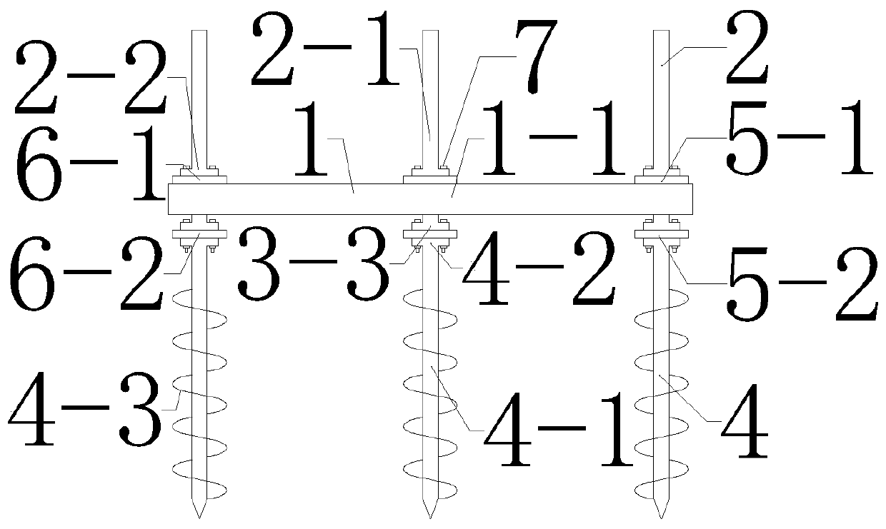
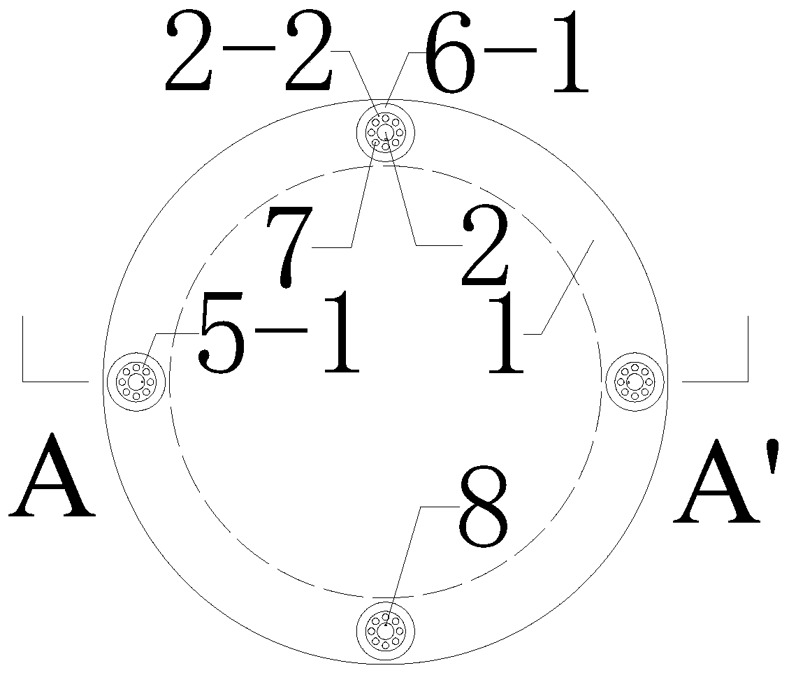
[0044] A composite circular foundation with screw piles comprises a circular foundation 1, a screw pile upper structure 2, a screw pile middle structure 3, a screw pile lower structure 4 and external power equipment.
[0045] Pre-grouting casing 1-2 at the outer side of the circular foundation body 1-1;
[0046] An upper flange 2-2 is welded along the lower edge of the screw pile superstructure body 2-1;
[0047] A lower flange 3-2 is welded on the upper edge of the middle structure body 3-1 of the screw pile, and an upper flange 3-3 is welded on the lower edge;
[0048] The upper part of the screw pile lower structure body 4-1 is welded with a lower flange 4-2, and the lower part is welded with a spiral blade 4-3.
[0049] The upper flange 2-2 and the lower flange 3-2 use the bolt and nut structure 7 to clamp the first circular steel plate 6-1 in the middle, forming a pair of flange structures 5-1 together, and the upper part of the screw pile The structure 2 and the middle...
Embodiment 2
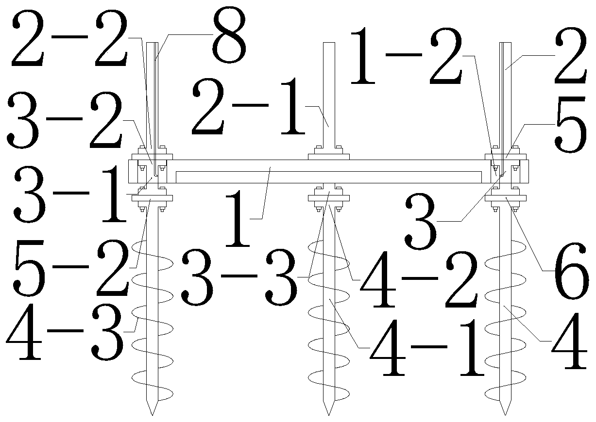
[0055] When the present invention is assembled on land, a crane should be used to erect the lower structure 4 of the screw pile, and other structures should be used to constrain it to keep it in an upright state; then the middle structure 3 of the screw pile should be lifted by a crane, And the upper flange 3-3 of the lower edge of the screw pile middle structure 3, the lower flange 4-2 of the upper edge of the screw pile lower structure 4, and the second circular steel plate 6-2 are matched with each other, and the flange 5 is manually tightened. The bolts and nuts 7 at -2 make the screw pile lower structure 4 and the screw pile middle structure 3 rigidly combined; then use the crane to lift the first circular foundation 1, and make the grouting casing 1 on the circular foundation 1 -2 through the middle structure 3 of the screw pile; finally, the upper structure 2 of the screw pile is hoisted by a crane, and the upper flange 2-2 structure of the lower edge of the upper struct...
Embodiment 3
[0057] When the present invention is laid down, after the whole structure is hoisted to the predetermined site, the screw pile partly penetrates below the mud surface through its own weight or external counterweight, and the screw pile will rotate around it under the drive of the external power device. With the rotation of the shaft, the screw blade 4-3 penetrating into the mud surface will generate a downward penetration force under the action of rotation, and the penetration force will pass through the lower structure body 4-1 of the screw pile, the flange 5-2, and the middle part of the screw pile in turn. The structural body 3-1, the flange 5-1 and the circular steel plate 6-1 are transferred to the circular foundation 1, driving the circular foundation 1 to sink to the predetermined position; during the sinking process, the rotation speed of the screw pile at different positions can be changed , to control the inclination of the circular foundation 1, to ensure that the bo...
PUM
 Abstract
Description
Claims
Application Information
 - R&D
- Intellectual Property
- Life Sciences
- Materials
- Tech Scout
- Unparalleled Data Quality
- Higher Quality Content
- 60% Fewer Hallucinations
Browse by: Latest US Patents, China's latest patents, Technical Efficacy Thesaurus, Application Domain, Technology Topic, Popular Technical Reports.
© 2025 PatSnap. All rights reserved.Legal|Privacy policy|Modern Slavery Act Transparency Statement|Sitemap|About US| Contact US: help@patsnap.com