
Display panel and display device

A display panel and display area technology, which is applied to identification devices, static indicators, instruments, etc., can solve the problems of high screen-to-body ratio restrictions, large camera size, and large frame area, so as to increase the screen-to-body ratio and realize narrow The design of the border, the effect of improving the viewing experience

Active Publication Date: 2021-10-15
WUHAN TIANMA MICRO ELECTRONICS CO LTD
View PDF6 Cites 0 Cited by
  • Summary
  • Abstract
  • Description
  • Claims
  • Application Information

AI Technical Summary

Problems solved by technology

[0003] The display panel in the electroluminescent display generally has a display area and a frame area. The frame area surrounds the display area. Optical devices such as cameras can be arranged in the frame area. Due to the large volume of the camera, the area occupied by the frame area is relatively large. large, resulting in greater restrictions in achieving high screen-to-body ratio and narrow bezel design

Method used


Image

  • Display panel and display device
  • Display panel and display device
  • Display panel and display device

Examples


Embodiment Construction

[0027] The specific implementation manners of a display panel and a display device provided by the embodiments of the present invention will be described in detail below with reference to the accompanying drawings. It should be noted that the described embodiments are only some of the embodiments of the present invention, but not all of the embodiments. Based on the embodiments of the present invention, all other embodiments obtained by persons of ordinary skill in the art without making creative efforts belong to the protection scope of the present invention.

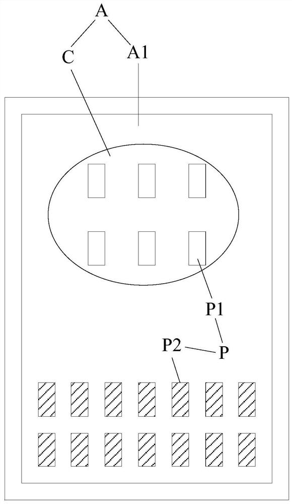
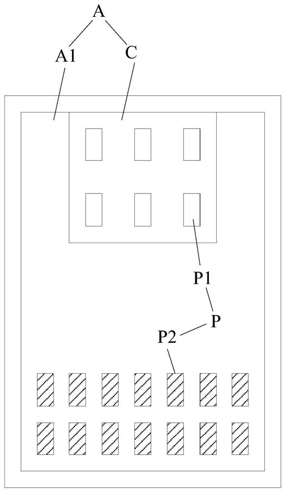
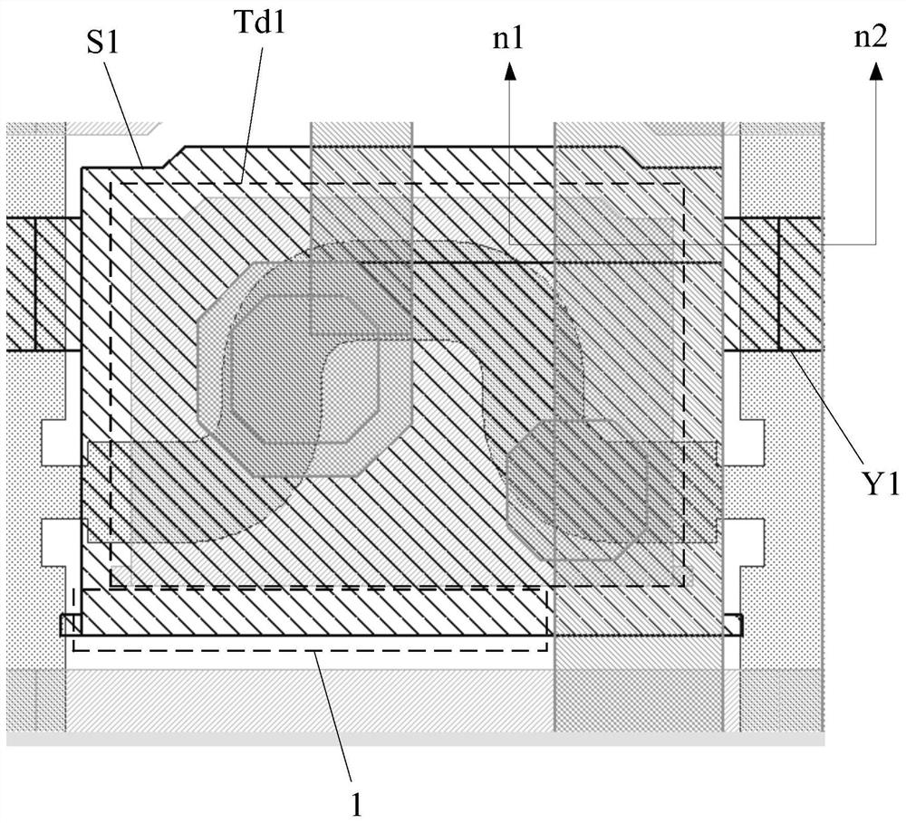
[0028] An embodiment of the present invention provides a display panel, such as Figure 1 to Figure 4 As shown, among them, figure 1 is a structural schematic diagram of a display panel, figure 2 is a structural schematic diagram of another display panel, figure 1 with figure 2 Only some pixels are shown in the image 3 is a schematic diagram of part of the layout in the first pixel, Figure 4 for along image...


PUM


Abstract

The invention discloses a display panel and a display device, and relates to the field of display technology. In an embodiment of the present invention, the display area includes a first display area and an optical component setting area, the first display area at least partially surrounds the optical component setting area, and when the optical component is set in the optical component setting area, it can prevent the optical component from being placed in the optical component setting area. The problem that the frame occupies a large area can make the frame narrower, increase the screen-to-body ratio, and achieve a narrow frame design. Moreover, by arranging the first pixels in the optical component arrangement area, the display effect of the picture can be improved, and the viewing experience of the user can be improved. In addition, by setting the light transmittance of the first bulk electrode to be greater than the light transmittance of the second bulk electrode, the optical component installation area can have a higher light transmittance, and the optical components are arranged in the optical component installation area. , so that the optical components can receive more light, so that the optical components can work normally and stably.

Description

technical field [0001] The invention relates to the field of display technology, in particular to a display panel and a display device. Background technique [0002] An electroluminescent display is a self-luminous device that can display without a backlight. Compared with a liquid crystal display, this kind of display can be made thinner and thinner because it does not need a backlight, so it can be applied to various scenarios. [0003] The display panel in the electroluminescent display generally has a display area and a frame area. The frame area surrounds the display area. Optical devices such as cameras can be arranged in the frame area. Due to the large volume of the camera, the area occupied by the frame area is relatively large. Large, resulting in greater restrictions in achieving high screen-to-body ratio and narrow bezel design. [0004] Then, how to improve the high screen-to-body ratio of the display panel and realize the narrow frame design is a technical pro...

Claims


Application Information

Patent Timeline
Patent Type & Authority Patents(China)
IPC IPC(8): G09F9/30G09G3/30
CPCG09F9/30G09G3/30
Inventor 张文帅
Owner WUHAN TIANMA MICRO ELECTRONICS CO LTD
Learn More