Gastric inspection device for digestive department

An inspection device and gastroenterology technology, applied in the medical field, can solve problems such as single function and patient discomfort

Inactive Publication Date: 2019-11-05
詹玮
View PDF8 Cites 2 Cited by
  • Summary
  • Abstract
  • Description
  • Claims
  • Application Information

AI Technical Summary

Problems solved by technology

[0002] The stomach inspection device is commonly used in the gastroenterology department, but the general stomach inspection device requires the patient to cooperate with changing the posture to detect the stomach disease, which will cause discomfort to the patient during the inspection process. At the same time, the function is relatively single

Method used


Image

  • Gastric inspection device for digestive department
  • Gastric inspection device for digestive department
  • Gastric inspection device for digestive department

Examples


specific Embodiment approach 1

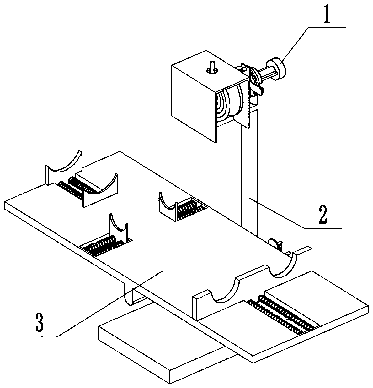
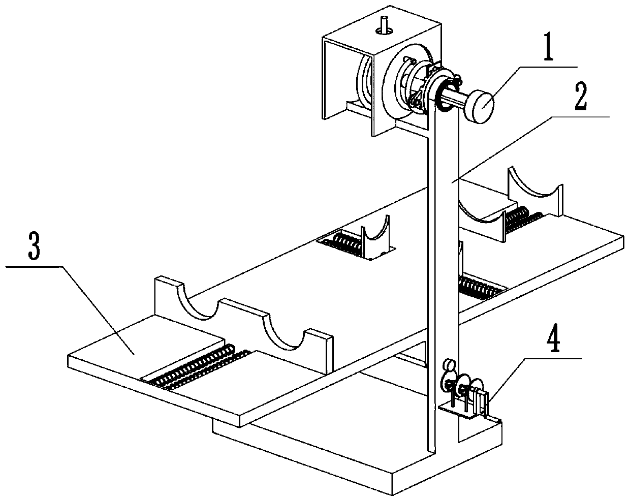
[0033] Combine below Figure 1-15 Describe this embodiment, a stomach examination device for gastroenterology, including an adjustment device 1, a support frame 2, a bed board assembly 3 and a speed change device assembly 4, characterized in that the adjustment device 1 and the support frame 2, the recliner assembly 3 is connected with the support frame 2, and the speed change device assembly 4 is fixedly connected with the support frame 2.

specific Embodiment approach 2

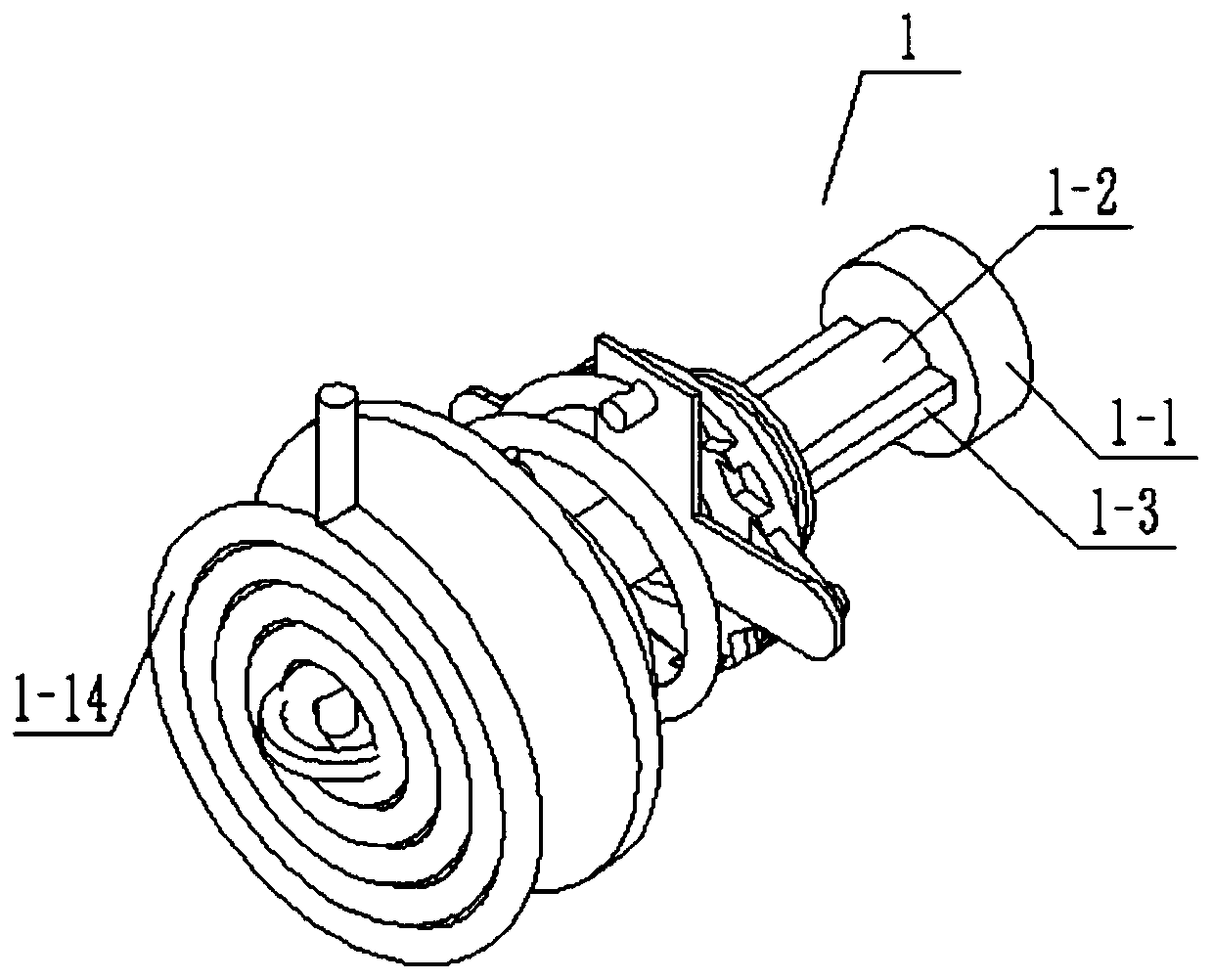
[0035] Combine below Figure 1-15Describe this embodiment, this embodiment will further explain the first embodiment, the adjustment device 1 includes a manual rotating rod 1-1, a connecting rod 1-2, a driving rectangular rod 1-3, a middle end frame 1-4, a torsion spring 1-5, drive plate 1-6, connecting column 1-7, ratchet teeth 1-8, shrapnel 1-9, one-way rod 1-10, one-way card slot 1-11, limit boss 1-12, Sleeve 1-13 and gastroscope 1-14, the connecting rod 1-2 is fixedly connected with the manual rotating rod 1-1, the driving rectangular rod 1-3 is fixedly connected with the connecting rod 1-2, the middle end frame 1-4 is connected with the The connecting rod 1-2 is fixedly connected, the torsion spring 1-5 is connected between the middle frame 1-4 and the driving disc 1-6, the connecting column 1-7 is fixedly connected with the driving disc 1-6, and the ratchet teeth 1-8 are connected with the The middle frame 1-4 is rotationally connected, the shrapnel 1-9 is fixedly conne...

specific Embodiment approach 3

[0038] Combine below Figure 1-15 This embodiment will be described. This embodiment will further describe the first embodiment. The support frame 2 includes a bottom plate 2-1, a vertical pole 2-2, a central turning hole 2-3, a vertical plate 2-4, a sliding Holes 2-5, rotating holes 2-6 and connecting plates 2-7, the vertical rod 2-2 is fixedly connected with the base plate 2-1, and the middle end rotating hole 2-3 is arranged on the vertical rod 2-2 On, the rotating hole 2-6 is arranged on the vertical pole 2-2, the vertical plate 2-4 is fixedly connected with the vertical pole 2-2, the sliding hole 2-5 is arranged on the vertical plate 2-4, and the connecting plate 2-7 is fixedly connected on the vertical rod 2-2, the sleeve pipe 1-13 is rotatably connected with the rotating hole 2-6, and the gastroscope 1-14 is cooperatively connected with the sliding hole 2-5.


PUM


Abstract

The invention aims to provide a gastric inspection device for digestive department; a gastroscope can be automatically retracted and placed through an adjustment device, and the detection efficiency is respectively up-regulated; a patient can be placed through a lying board combined body; at the same time, the patient posture is convenient to adjust through a speed change device combined body, andthe gastroscope inspection device includes an adjustment device, a support outer frame, the lying board combined body and the speed change device combined body; a drive conical disc rotates once to drive rotation of a sliding hole, then the sliding hole is driven to rotate, the angle of the patient lying on a bottom board is convenient to change, and an image in a stomach of the patient is collected by the gastroscope conveniently; a manual rotating rod is pushed manually, and a ratchet tooth is separated from a one-way clamping groove, so that a driving disk rotates in reverse direction under driving of the torsion force of a torsion spring, and the gastroscope is rolled in reverse direction through the reverse rotation of the driving disk, so as to realize automatic recovery of the gastroscope; a manual threaded rod is adjusted manually, and the use position of a threaded sleeve is changed through the manual threaded rod.

Description

technical field [0001] The invention relates to the medical field, in particular to a stomach examination device for gastroenterology. Background technique [0002] The stomach inspection device is commonly used in the gastroenterology department, but the general stomach inspection device requires the patient to cooperate with changing the posture to detect the stomach disease, which will cause discomfort to the patient during the inspection process. At the same time, the function is relatively single. Contents of the invention [0003] The purpose of the present invention is to provide a stomach inspection device for gastroenterology, which can automatically retract and retract the gastroscope through the adjustment device, and respectively increase the detection efficiency; the patient can be placed through the lying board assembly; at the same time, the patient can be adjusted conveniently through the speed change device assembly attitude. [0004] The purpose of the ...

Claims


Application Information

Patent Timeline
Patent Type & Authority Applications(China)
IPC IPC(8): A61G13/02A61G13/00A61G13/10A61G13/12A61B1/00
CPCA61B1/00147A61G13/0018A61G13/02A61G13/101A61G13/12A61G13/1295
Inventor 詹玮廖欣刘静张汝一杨勤姬清华
Owner 詹玮
Why Eureka
Try Eureka