Easy-disassembled ultrasonic vibrator

An ultrasonic and easy-to-disassemble technology, applied in the field of easy-to-disassemble ultrasonic vibrators, can solve problems such as difficult disassembly of ultrasonic vibrators

Pending Publication Date: 2019-11-05
邱瑞权
View PDF0 Cites 2 Cited by
  • Summary
  • Abstract
  • Description
  • Claims
  • Application Information

AI Technical Summary

Problems solved by technology

[0005] The easy-to-disassemble ultrasonic vibrator of the present invention solves the problem that the ultrasonic vibrator in electrical appliances is difficult to disassemble in the prior art

Method used


Image

  • Easy-disassembled ultrasonic vibrator
  • Easy-disassembled ultrasonic vibrator
  • Easy-disassembled ultrasonic vibrator

Examples


Embodiment 1

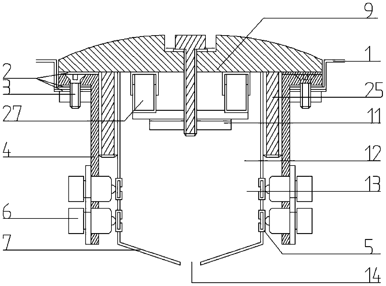
[0034] Such as figure 1 As shown, the easy-to-detach ultrasonic vibrator includes a vibrator mounting base 4 installed on the cleaning container wall 1. The vibrator mounting base 4 includes a mutually perpendicular mounting ring portion and a mounting barrel portion, and the mounting ring portion is located at the center of the mounting barrel portion. In the upper part, the installation ring part is connected with the cleaning container wall 1 through the first fixing screw 3 to realize the fixation of the vibrator mounting seat 4; the inner wall of the installation barrel part is provided with a first internal thread. The vibrator fixing seat 25 includes a fixed ring portion and a fixed barrel portion perpendicular to each other. The fixed ring portion is located on the upper part of the fixed barrel portion. The width and size of the fixed ring portion ensure that the installation ring portion can be covered, and the fixed ring portion There is a sealing shock-absorbing pa...

Embodiment 2

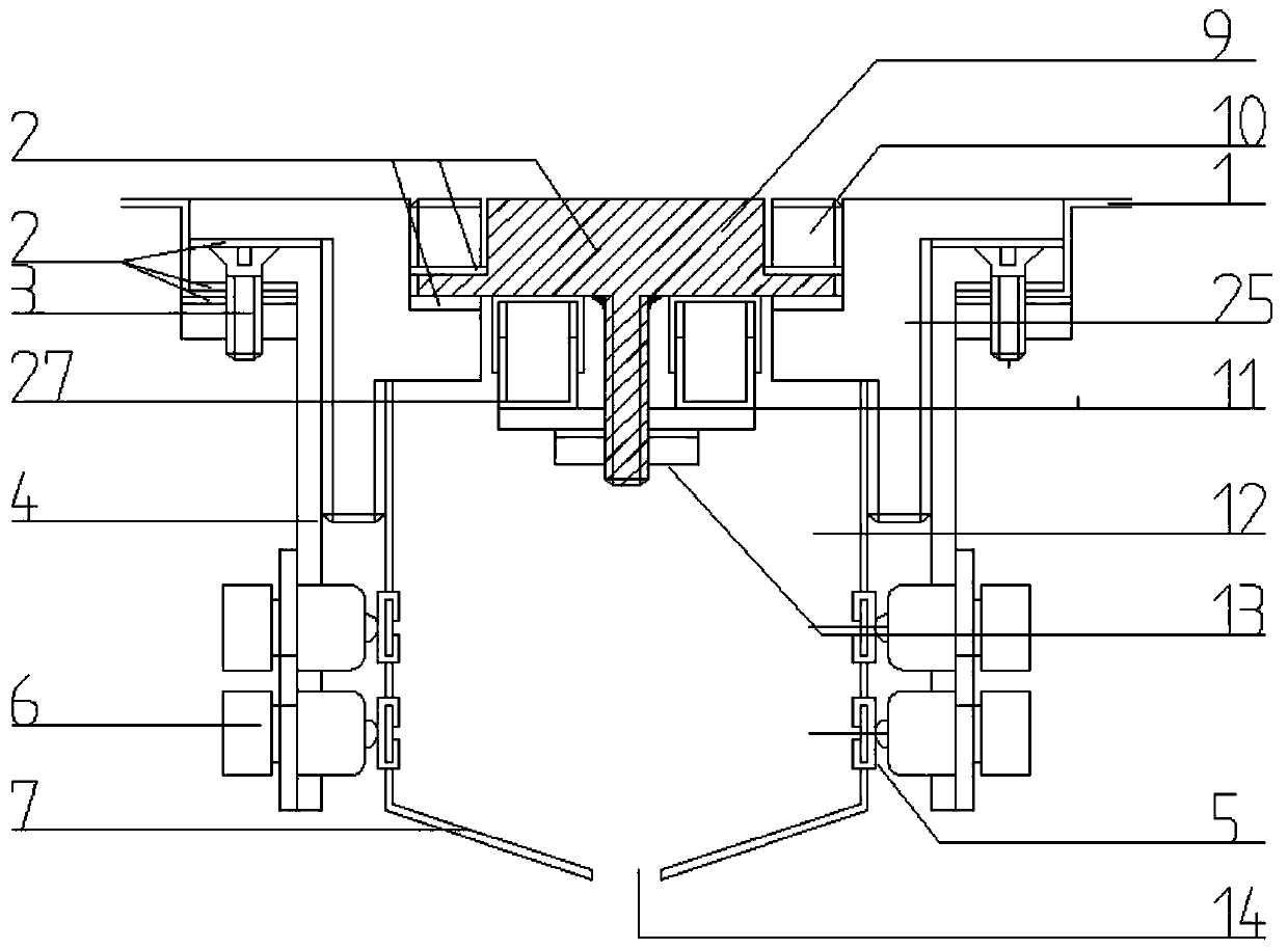
[0040] The difference between this solution and the first embodiment is that the radiating surface of the clamped iron on the vibrator is an arc-shaped radiating surface. Such as figure 2 As shown, the arc radiation surface has a wider radiation range than the plane radiation surface, and is suitable for larger spaces.

Embodiment 3

[0042] The difference between this solution and Embodiment 1 and Embodiment 2 is that: the top of the central screw is welded to the bottom of the clamp iron on the vibrator. Such as image 3 with Figure 4 As shown, compared with the first embodiment, the connection between the central screw of this solution and the clamping iron on the vibrator is tighter.


PUM


Abstract

The invention belongs to the field of electric energy utilization, and provides an easy-disassembled ultrasonic vibrator for the problem of difficult disassembly of ultrasonic vibrators in electric appliances in the prior art. The easy-disassembled ultrasonic vibrator comprises a vibrator mounting base mounted on the wall of a cleaning container; the vibrator mounting base is detachably connectedwith a vibrator barrel fixed base; a vibrator mechanism is arranged in the center position of the upper part of the vibrator fixed base; the vibrator mechanism comprises a vibrator upper clamping iron, a piezoelectric ceramic body and a vibrator lower clamping iron fixed by center screws in sequence from top to bottom; the vibrator upper clamping iron is used as a vibrator radiation surface of thepiezoelectric ceramic body; the vibrator upper clamping iron and the vibrator barrel fixed base are fixed through a third fixed screw; the vibrator fixed base is connected with a vibrator barrel wallfor holding ultrasonic devices inside through threads; the piezoelectric ceramic body and the vibrator lower clamping iron both extend into the vibrator barrel wall; an electric conducting ring is arranged at the lower part of the side wall of the vibrator barrel wall; multiple sets of elastic power transmission electrodes are arranged at the lower part of the vibrator mounting base; the electricconducting ring is used for transmitting power into the vibrator barrel wall; and the third fixed screw is provided with a spanner jaw hole.

Description

technical field [0001] The invention belongs to the field of electric energy utilization, and in particular relates to an easily disassembled ultrasonic vibrator. Background technique [0002] Ultrasonic piezoelectric ceramic vibrators have significant irreplaceable advantages in the fields of atomization and cleaning, and their applications are becoming more and more extensive. There are two working methods of the existing ultrasonic piezoelectric ceramic vibrator: one is an independent sealed and waterproof piezoelectric ceramic vibrator head, which is put into water when in use, and can be cleaned after being connected to the power supply, which belongs to the portable category. cleaning tools. The second way is to install the ultrasonic piezoelectric ceramic vibrator on the container wall, wherein the radiating surface of the vibrator is fixed on the inner wall of the container facing the working medium in the container, and the fixing nut of the vibrator is fixed on th...

Claims


Application Information

Patent Timeline
Patent Type & Authority Applications(China)
IPC IPC(8): B08B3/12B06B1/06
CPCB06B1/0644B08B3/12
Inventor 邱瑞权
Owner 邱瑞权
Why Eureka
Try Eureka