Muffler for motorcycle exhaust pipe
A technology for motorcycles and mufflers, applied in exhaust treatment, exhaust devices, mufflers, etc., can solve problems such as engine power drop, exhaust pipe blockage, oil leakage, etc. Effect
- Summary
- Abstract
- Description
- Claims
- Application Information
AI Technical Summary
Problems solved by technology
Method used
Image
Examples
Embodiment 1
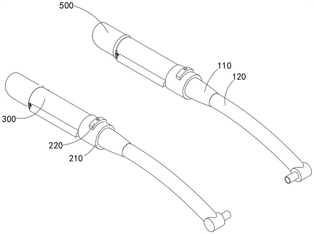
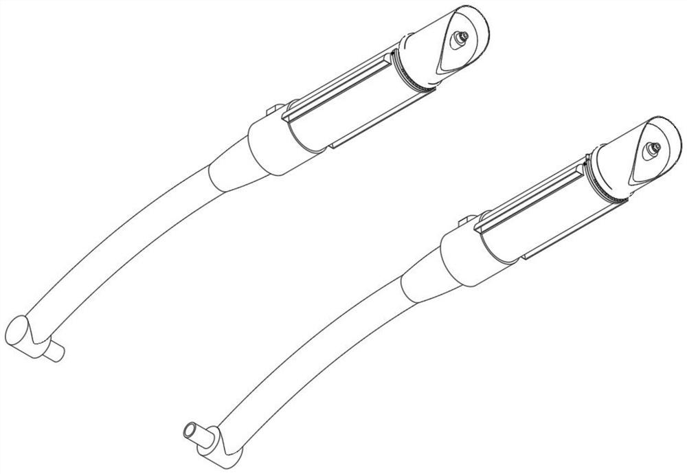
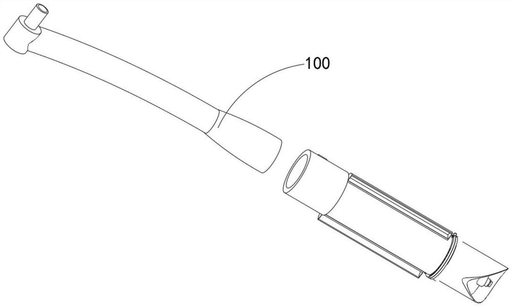
[0055] combine Figure 4 , 5 , 8, 10 and 11, the motorcycle exhaust pipe muffler provided by the present invention includes a connecting mechanism 100, an exhaust gas displacement control mechanism 200, a noise reduction combination 300, a water circulation heat dissipation combination 400 and an assembled tail end mechanism 500, wherein the exhaust gas The displacement control mechanism 200 is fixedly installed on the connection mechanism 100, and the noise reduction combination 300 can be assembled on the exhaust gas displacement control mechanism 200. In addition, the water circulation heat dissipation combination 400 is installed outside the noise reduction combination 300 for the discharge of heat in the exhaust gas. The tail end mechanism 500 is installed on the sound-absorbing combination 300 .
[0056] The connecting mechanism 100 includes an arc pipe 110, a terminal head 120 and a tapered pipe 130, wherein the exhaust gas displacement control mechanism 200 includes a...
Embodiment 2
[0059] combine Figure 4 As shown, in the above embodiment, the connecting mechanism 100 includes an arc tube 110 , an end 120 welded on the arc tube 110 , and a tapered tube 130 installed at one end of the arc tube 110 .
[0060] By adopting the above-mentioned technical scheme, according to the use of motorcycle exhaust pipes today, a trapezoidal tapered pipe 130 is fixedly welded at one end of the arc pipe 110, and a trapezoidal pipe 130 is formed between the tapered pipe 130 and the inner cavity of the safety outer cylinder 210. The large volume space can make the exhaust gas generate enough negative pressure after entering the space, and can facilitate the rapid exchange of airflow during engine operation.
Embodiment 3
[0062] combine Figure 5 As shown, in the above embodiment, the fine-tuning part includes a screw rod 240 threadedly connected to the inner core ring 230, a soft screw rod 250 movable in the annular groove in the middle of the inner core ring 230, and teeth engaging with the soft screw rod 250. Article 260.
[0063] By adopting the above-mentioned technical solution, by penetrating the top ends of the two screw rods 240 to the outside of the safety outer cylinder 210, when the device is adapted to different types of engines, in order to quickly adjust the exhaust diameter of the internal cavity of the device on the exhaust gas load Therefore, the fan-shaped baffles are movably installed inside the inner core ring 230, and the diameter of the circular notch inside the inner core ring 230 for exhaust gas discharge is controlled by fine-tuning the two screw rods 240, thereby improving the performance of the device on different Model suitability.
PUM
 Abstract
Description
Claims
Application Information
 - R&D
- Intellectual Property
- Life Sciences
- Materials
- Tech Scout
- Unparalleled Data Quality
- Higher Quality Content
- 60% Fewer Hallucinations
Browse by: Latest US Patents, China's latest patents, Technical Efficacy Thesaurus, Application Domain, Technology Topic, Popular Technical Reports.
© 2025 PatSnap. All rights reserved.Legal|Privacy policy|Modern Slavery Act Transparency Statement|Sitemap|About US| Contact US: help@patsnap.com


