
An automatic feeding and slotting device for tooth bars

An automatic feeding and tooth bar technology, which is applied to the grinding drive device, grinding feed motion, manufacturing tools, etc., can solve the problems of manual replacement of tooth bars, uneven opening grooves, affecting the use of tooth bars, etc. The slotting device is flexible, the slotting quality is good, and the effect of improving the slotting quality

Active Publication Date: 2021-06-25
HAIYAN HUILIAN GENERAL FITTING
View PDF0 Cites 0 Cited by
  • Summary
  • Abstract
  • Description
  • Claims
  • Application Information

AI Technical Summary

Problems solved by technology

The ones located in other parts are generally renamed tooth bars. In addition, they are also used in construction and decoration. When the ceiling is decorated, they are mostly used to connect the roof and the ceiling joist. During the production process of the tooth bar, the tooth bar is conveniently rotated and installed. Most of the strips will be provided with a straight slot at one end of the strip, but the existing slotting equipment has low processing efficiency, and the opening slot is not smooth, and most of them will be in the shape of deep in the middle of the slot and shallow on both sides, which will affect the use of the strip. The processing efficiency of the existing equipment is low, and the teeth need to be replaced manually, which is labor-intensive

Method used


Image

  • An automatic feeding and slotting device for tooth bars
  • An automatic feeding and slotting device for tooth bars
  • An automatic feeding and slotting device for tooth bars

Examples


Embodiment Construction

[0018] In order to make the object, technical solution and advantages of the present invention clearer, the present invention will be further described in detail below with reference to the accompanying drawings and embodiments. However, it should be understood that the specific embodiments described here are only used to explain the present invention, and are not intended to limit the scope of the present invention. Also, in the following description, descriptions of well-known structures and techniques are omitted to avoid unnecessarily obscuring the concept of the present invention.

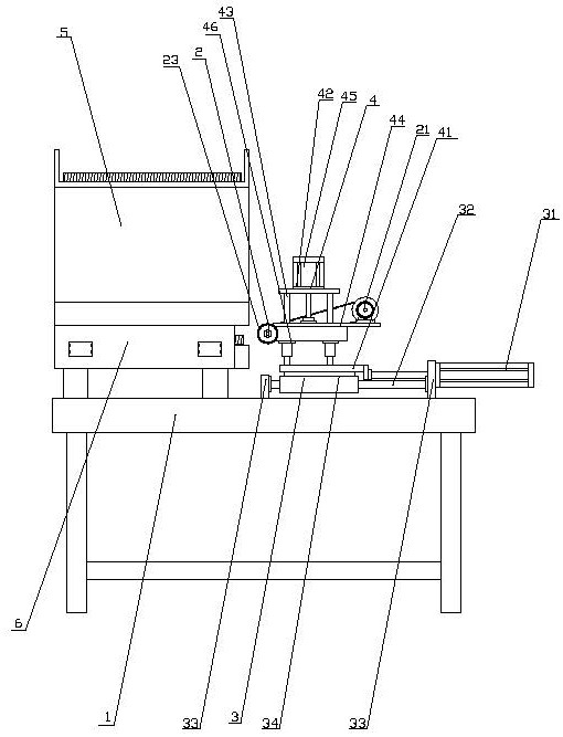
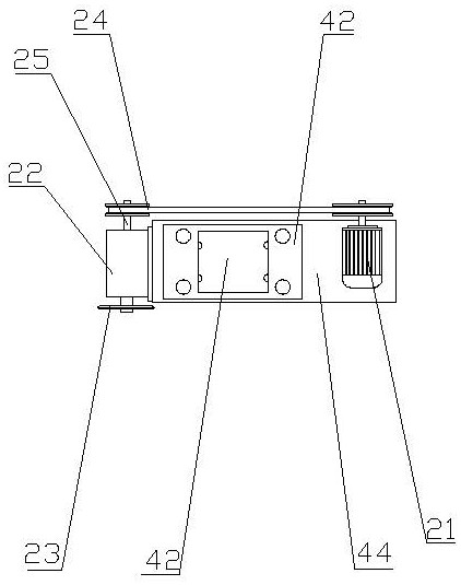
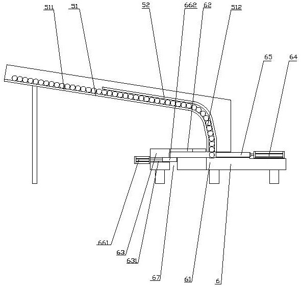
[0019] refer to figure 1 , figure 2 and image 3, an automatic slotting device for automatic feeding of tooth bars according to the present invention, comprising a frame 1, a slotting device 2, a slotting device traverse mechanism 3, a slotting device lifting device 4, a tooth bar feeding trough 5, an automatic feeding Device 6, the upper end of the frame 1 is horizontally provided with a ...


PUM


Abstract

The invention discloses an automatic grooving device for automatic feeding of tooth bars, comprising a frame, a grooving device, a transverse movement mechanism of the grooving device, a lifting device of the grooving device, a feeding chute for tooth bars, and an automatic feeding device. The upper end of the frame is provided with a transverse movement mechanism of the slotting device, and the upper end of the moving part of the transverse movement mechanism of the slotting device is provided with a lifting device of the slotting device. Cooperate to realize the automatic feeding and unloading of the tooth bar, improve the slotting efficiency of the tooth bar, improve the slotting quality, reduce the labor intensity, and set the slotting device lifting device and the slotting device transverse mechanism to drive the slotting device to move up and down, left and right, The slotting device is more flexible, improves the slotting efficiency of the tooth bar, and improves the slotting accuracy of the tooth bar. The lifting device of the slotting device drives the slotting device to slot the tooth bar from bottom to top or from top to bottom. Even better, the notches are neat and the depth of the grooves is consistent.

Description

technical field [0001] The invention relates to the technical field of tooth bar production equipment, in particular to the technical field of tooth bar slotting devices. Background technique [0002] The tooth bar is the tooth, also known as the lead screw. It is the name of furniture parts in the Ming and Qing Dynasties. It generally refers to the parts connected between the two legs under the surface frame, and the furniture with a waist is the main connecting part below the waist. The ones located in other parts are generally renamed tooth strips. In addition, they are also used in construction and decoration. When the ceiling is decorated, they are mostly used to connect the roof and the ceiling keel. During the production of the tooth strips, the tooth strips are conveniently rotated and installed. The strips usually have a straight slot at one end of the strip, but the existing slotting equipment has low processing efficiency and the opening slot is not smooth, and m...

Claims


Application Information

Patent Timeline
Patent Type & Authority Patents(China)
IPC IPC(8): B24B19/02B24B41/00B24B41/02B24B47/06
CPCB24B19/02B24B41/005B24B41/02B24B47/06
Inventor 屠马军
Owner HAIYAN HUILIAN GENERAL FITTING
Learn More