
Continuous rope-shaped jetting water washer

A water-washing machine and rope-like technology, which is applied in liquid/gas/vapor rope-like fabric processing, textile material carrier processing, textile material processing equipment configuration, etc. It can reduce the energy consumption of equipment operation, save floor space and save resources.

Pending Publication Date: 2019-11-05
诺唯格机械制造(江苏)有限公司
View PDF0 Cites 8 Cited by
  • Summary
  • Abstract
  • Description
  • Claims
  • Application Information

AI Technical Summary

Problems solved by technology

The traditional rope washing machine has many defects such as large floor area, high manufacturing cost, high energy consumption for equipment operation, poor washing effect, large water consumption, and low production efficiency.

Method used


Image

  • Continuous rope-shaped jetting water washer
  • Continuous rope-shaped jetting water washer
  • Continuous rope-shaped jetting water washer

Examples


Embodiment 1

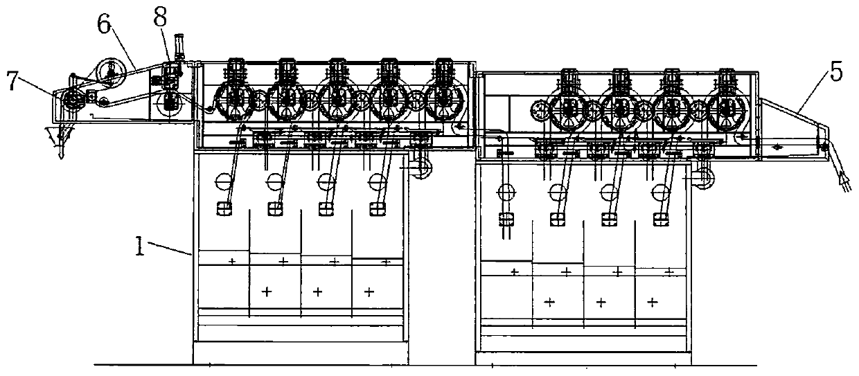
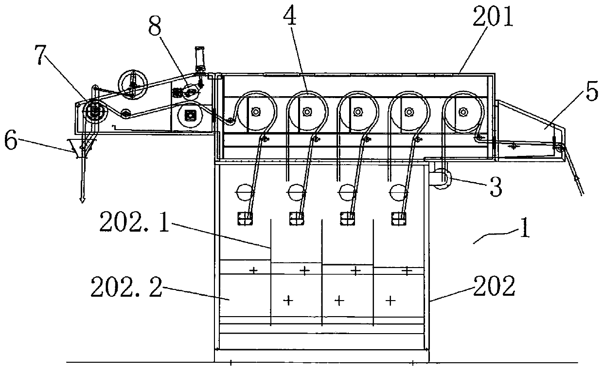
[0071] The cloth lifting mechanism 4 includes a pressure roller assembly 402A arranged up and down and a cloth lifting wheel assembly 401A. The cloth lifting wheel assembly 401A includes a transmission shaft 401.1A, and the transmission shaft 401.1A is arranged on the left and right boxes of the upper box body 201. Between the walls, one end of the transmission shaft 401.1A is provided with a driving motor 401.3A, and the middle part of the transmission shaft 401.1A is provided with a cloth lifting wheel 401.2A. The disc 401.2.1A on the shaft 401.1A, a plurality of rungs 401.2.2A are arranged between the left and right discs 401.2.1A, the plurality of rungs 401.2.2A are located on the same circumference, and the plurality of rungs 401.2.2A Arranged at intervals, there is a gap between every two adjacent crosspieces 401.2.2A;

[0072] The pressure roller assembly 402A includes a cylinder base 402.2A, on which a cylinder 402.1A is hinged, and the cylinder 402.1A is installed on ...

Embodiment 2

[0077] The cloth lifting mechanism 4 includes a cloth lifting wheel assembly 401B, and the cloth lifting wheel assembly 401B includes a transmission shaft 401.1B, and the transmission shaft 401.1B is arranged between the left and right box walls of the upper box body 201, and the transmission shaft One end of 401.1B is provided with a driving motor 401.3B, and the middle part of the transmission shaft 401.1B is provided with a cloth lifting wheel 401.2B. .1B, multiple crosspieces 401.2.2B are arranged at intervals between the left and right discs 401.2.1B, the multiple crosspieces 401.2.2B are located on the same circumference, and there are embedded between two adjacent crosspieces 401.2.2B Outwardly protruding rubber strips 401.2.3B;

[0078] The disc 401.2.1B and the crosspiece 401.2.2B are made of stainless steel.

[0079] Since the outer surface of the cloth lifting wheel is evenly embedded with a plurality of raised rubber strips, when the fabric is wrapped around the s...


PUM


Abstract

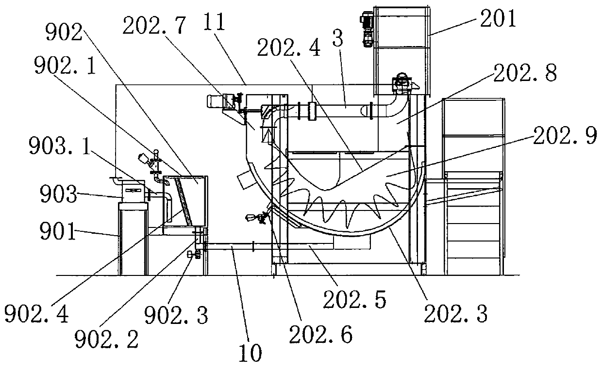
The invention relates to a continuous rope-shaped jetting water washer. The continuous rope-shaped jetting water washer comprises multiple serial washing units (1), and each washing unit (1) comprisesan upper box (201) and a lower box (202). The continuous rope-shaped jetting water washer is characterized in that multiple vertical partition plates (202.1) are arranged in the lower boxes (202) inthe cloth feeding direction at intervals, each lower box (202) is divided into multiple washing cavities (202.2) through the corresponding partition plates (202.1), every two adjacent washing cavities(202.2) are connected through a distribution pipe (3), and the distribution pipes (3) are of S-shaped structures in the vertical direction and of Z-shaped structures in the horizontal direction. Thecontinuous rope-shaped jetting water washer has the advantages that the occupation space is saved, the manufacturing cost is lowered, the washing effect is improved, and the water consumption is lowered.

Description

technical field [0001] The invention relates to a continuous rope jet washing machine, which belongs to the technical field of printing and dyeing equipment. Background technique [0002] The rope washing machine is referred to as the rope washing machine, which is usually used for washing the fabric after dyeing, so as to clean the residual floating color paste on the surface of the fabric and further fix the color of the fabric. The traditional rope washing machine has many defects such as large floor space, high manufacturing cost, high energy consumption for equipment operation, poor washing effect, large water consumption, and low production efficiency. Contents of the invention [0003] The technical problem to be solved by the present invention is to provide a continuous rope jet washing machine that saves floor space, reduces manufacturing costs, reduces equipment operation energy consumption, improves washing effect, and saves water consumption in view of the abov...

Claims


Application Information

Patent Timeline
IPC IPC(8): D06B3/26D06B23/20D06B23/04
CPCD06B3/26D06B23/20D06B23/04
Inventor 居品良
Owner 诺唯格机械制造(江苏)有限公司
Learn More