Water-permeable spur dike capable of adjusting angle with river bank

A river bank and angle technology, applied in the direction of pier, quay wall, embankment, etc., can solve the problems of large impact force of water flow, easy to be damaged, poor stability, etc., and achieve the effect of slowing down the flow velocity of water flow, ensuring survival rate and reducing impact

Pending Publication Date: 2019-11-05
NORTH CHINA UNIV OF WATER RESOURCES & ELECTRIC POWER
View PDF0 Cites 5 Cited by
  • Summary
  • Abstract
  • Description
  • Claims
  • Application Information

AI Technical Summary

Problems solved by technology

[0003] The current spur dikes are basically gravity spur dikes. Once built, it is impossible to dismantle them at will. Moreover, the traditional spur dikes not only have slow construction speed, high engineering cost, poor stability, and heavy maintenance workload at ordinary times. It is also very difficult to carry out flood control and rescue on the spur dam in critical moments, and it cannot play the role of flood control and bank protection and stabilizing t

Method used


Image

  • Water-permeable spur dike capable of adjusting angle with river bank
  • Water-permeable spur dike capable of adjusting angle with river bank
  • Water-permeable spur dike capable of adjusting angle with river bank

Examples


Example Embodiment

[0027] Example 1

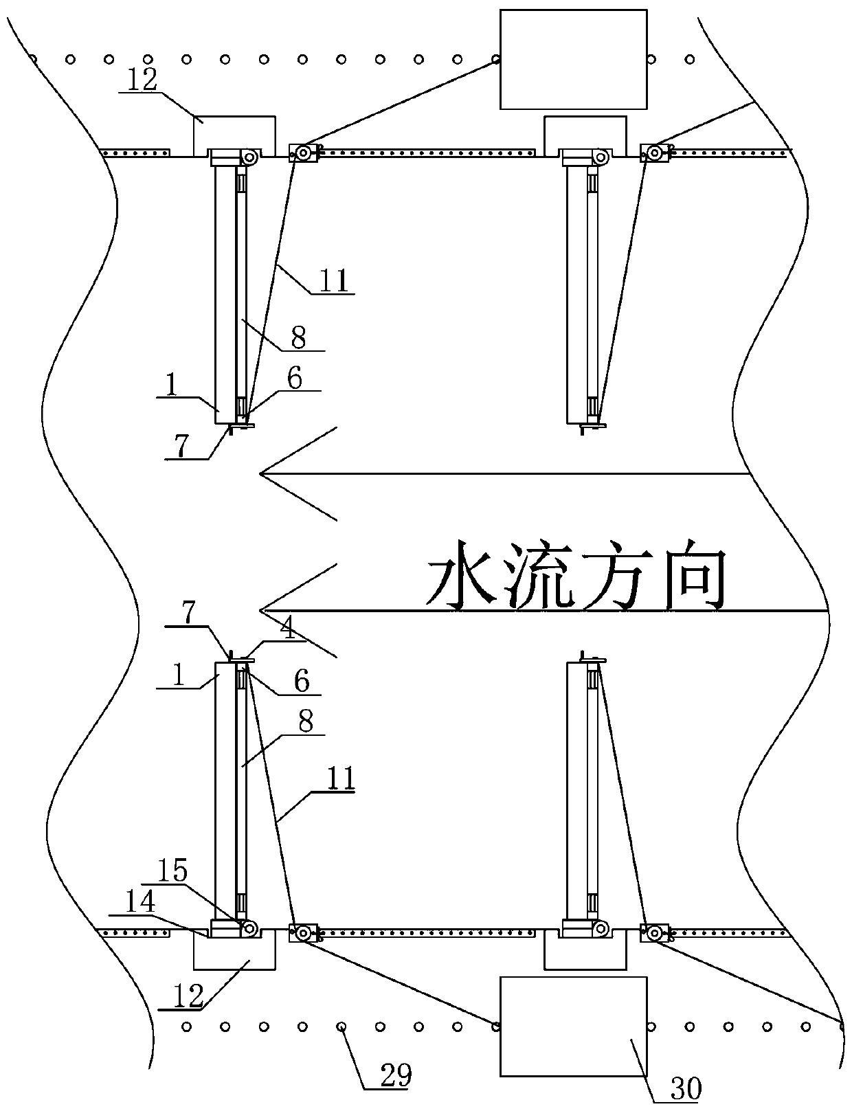
[0028] like figure 1 , figure 2 As shown, the permeable spur group is composed of multiple permeable spur dike intervals. The permeable spur dike includes steel sheet piles 12 vertically arranged on one side of the river. Two fixed horizontal columns 24 are provided, and the fixed horizontal columns 24 are fixed in the embankment. A groove 14 is vertically opened in the middle of the front side of the upper section of the steel sheet pile 12, and a cuboid is vertically arranged in the river channel on the front side of the groove 14. The shape of the dam body has a plurality of rectangular water passage holes on the dam body.

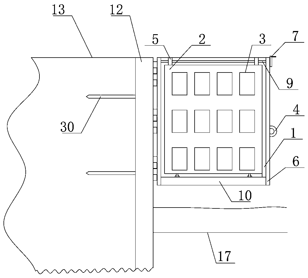
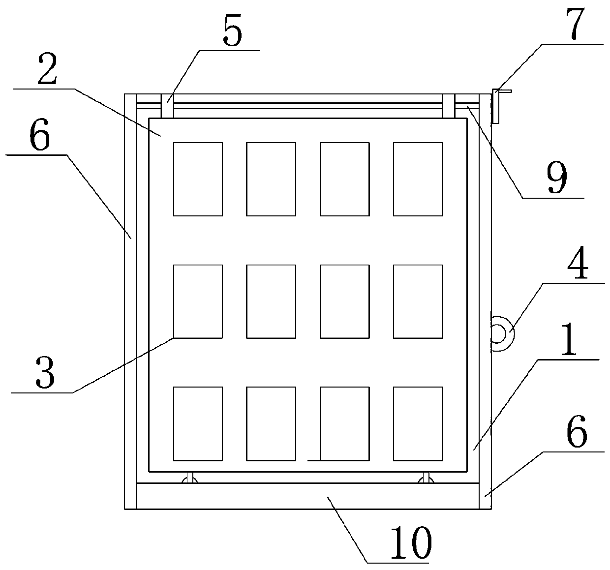
[0029] like image 3 As shown, the dam body includes a main dam body 1 and an auxiliary dam body 2 arranged on the water-facing surface in front of the main dam body. Both the main dam body 1 and the auxiliary dam body 2 have a plurality of rectangular water passage holes evenly corresponding to each other. The left and right end...

Example Embodiment

[0038] Example 2

[0039] The difference between embodiment 2 and embodiment 1 is that the structure of the traction mechanism is different.

[0040] like Figure 8 , Figure 9 As shown, the river bank 13 is provided with a tractor 30, and the moving track of the tractor 30 is parallel to the river bank. Along the moving track line 26 of the tractor 30, a plurality of fixed pile grooves 29 are evenly opened on the river bank 13. The fixed piles installed in the adjacent fixed pile grooves 29 at both ends are used to limit the position of the tractor 30 .

[0041] like Figure 8 As shown, on the edge of the river bank, a fixed track 22 is arranged parallel to the river, and the bottom of the fixed track 22 is uniformly provided with a plurality of safety holes 23 along the direction of the track. The fixed track 22 is provided with a guide platform 16, and the bottom of the guide platform 16 It is fixed in the fixed track 22 and can move back and forth along the fixed track...

Example Embodiment

[0046] Example 3

[0047] The difference between embodiment 3 and embodiment 2 lies in the structure of the dam body.

[0048] The water-facing surface of the dam body is covered with a bionic plant grass mat to reduce the impact of fish and other aquatic organisms on the dam body and effectively ensure the survival rate of aquatic organisms.


PUM


Abstract

The invention discloses a water-permeable spur dike capable of adjusting the angle with a river bank. The water-permeable spur dike comprises a steel plate pile vertically arranged on one side of a riverway. A groove is vertically formed in the middle of the front side of the steel plate pile. A cuboid dike boy is vertically arranged at the position, on the front side of the groove, in the riverway. The dike body comprises a main dike body and an auxiliary dike body arranged in front of the main dike body to serve as an upstream face. A traction ring is transversely arranged at the lower position of the middle of the offshore face of the dike body. A steel twisted rope is fixed to the traction ring. The nearshore face of the dike body and the groove of the steel plate pile are hinged and fixed together through a hinge. The other end of the steel twisted rope is connected with a traction mechanism on the river bank. According to the water-permeable spur dike, the included angle betweenthe dike body and the river bank according to the requirement of the actual fairway depth, the size of water passing holes of the dike body can be controlled by changing the position of the auxiliarydike body, and therefore the flow speed of water flow is reduced stage by stage when water flow passes through a water-permeable spur dike group.

Description

technical field [0001] The invention relates to the technical field of waterway regulation, in particular to a permeable spur dam whose angle with the river bank can be adjusted. Background technique [0002] my country has a vast territory and rivers weave vertically and horizontally. Spur dam is the most commonly used regulation structure in river regulation projects. Its main function is to narrow the river channel when it is not submerged, increase the flow velocity to scour the shoal, and cause circulation after submersion, guide sand laterally, increase Channel water depth; silt up river bank, protect river bank, etc. [0003] The current spur dikes are basically gravity spur dikes. Once built, it is impossible to dismantle them at will. Moreover, traditional spur dikes not only have slow construction speed, high engineering cost, poor stability, and heavy maintenance workload at ordinary times. It is very difficult to carry out flood control and rescue on the spur dik...

Claims


Application Information

Patent Timeline
IPC IPC(8): E02B3/06
CPCE02B3/06
Inventor 严军蔡显赫吕亚军付雪伟
Owner NORTH CHINA UNIV OF WATER RESOURCES & ELECTRIC POWER
Why Eureka
Try Eureka