Hydraulic impact rotating cylinder fishway
A hydraulic shock and rotary drum technology, applied in water conservancy engineering, marine engineering, climate change adaptation, etc., can solve the problem of low and poor fish passing efficiency, only suitable for fish that like to migrate on the surface and have jumping habits, and the design is difficult and other problems to achieve the effect of ensuring fish safety, shortening fish crossing time, and reducing physical energy consumption
- Summary
- Abstract
- Description
- Claims
- Application Information
AI Technical Summary
Problems solved by technology
Method used
Image
Examples
Embodiment 1
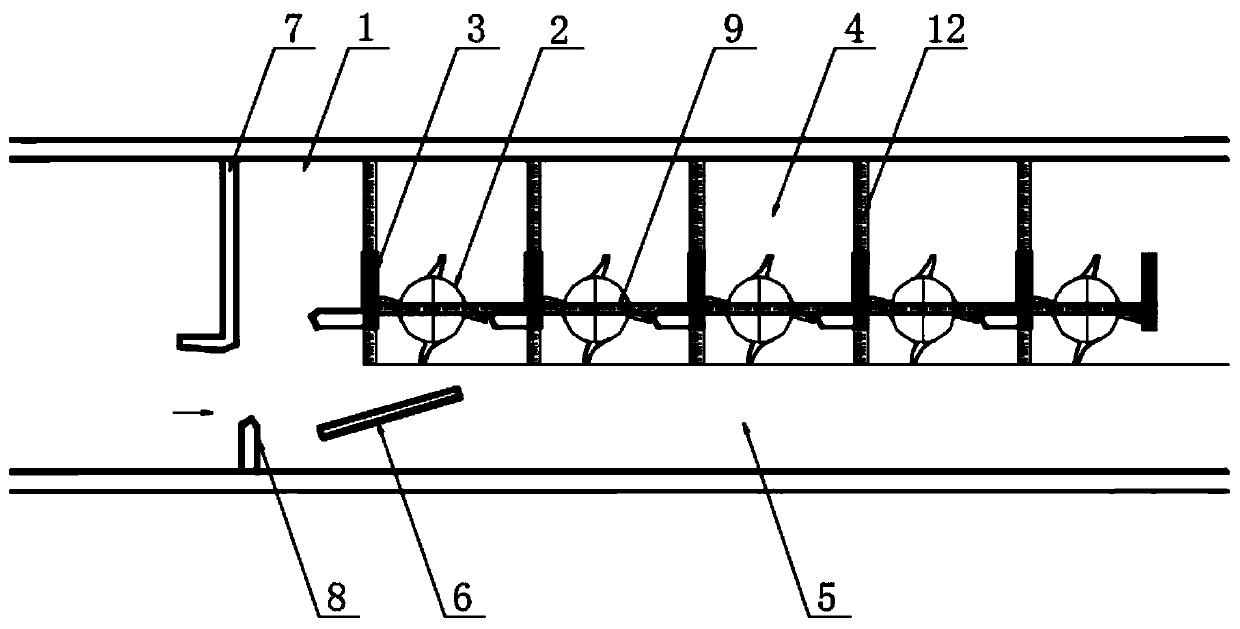
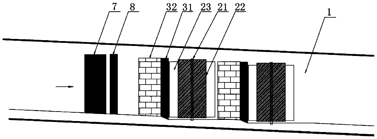
[0035] Refer to the attached Figure 1-4 , this embodiment is a hydraulic impact rotary cylinder fishway, including a gate base groove 1 fixed on the river bed at the bottom of the fishway entrance, the entrance side of the gate base groove 1 is provided with a diversion component, and the middle position of the gate base groove 1 is Along the water flow direction, a row of water flow regulating mechanisms 2 and baffle assemblies 3 arranged at intervals and crossings are arranged, and the fishway is divided into two parts, the slow flow area 4 and the rapid flow area 5, and the entrance of the rapid flow area 5 is provided with an adjusting partition 6 ;
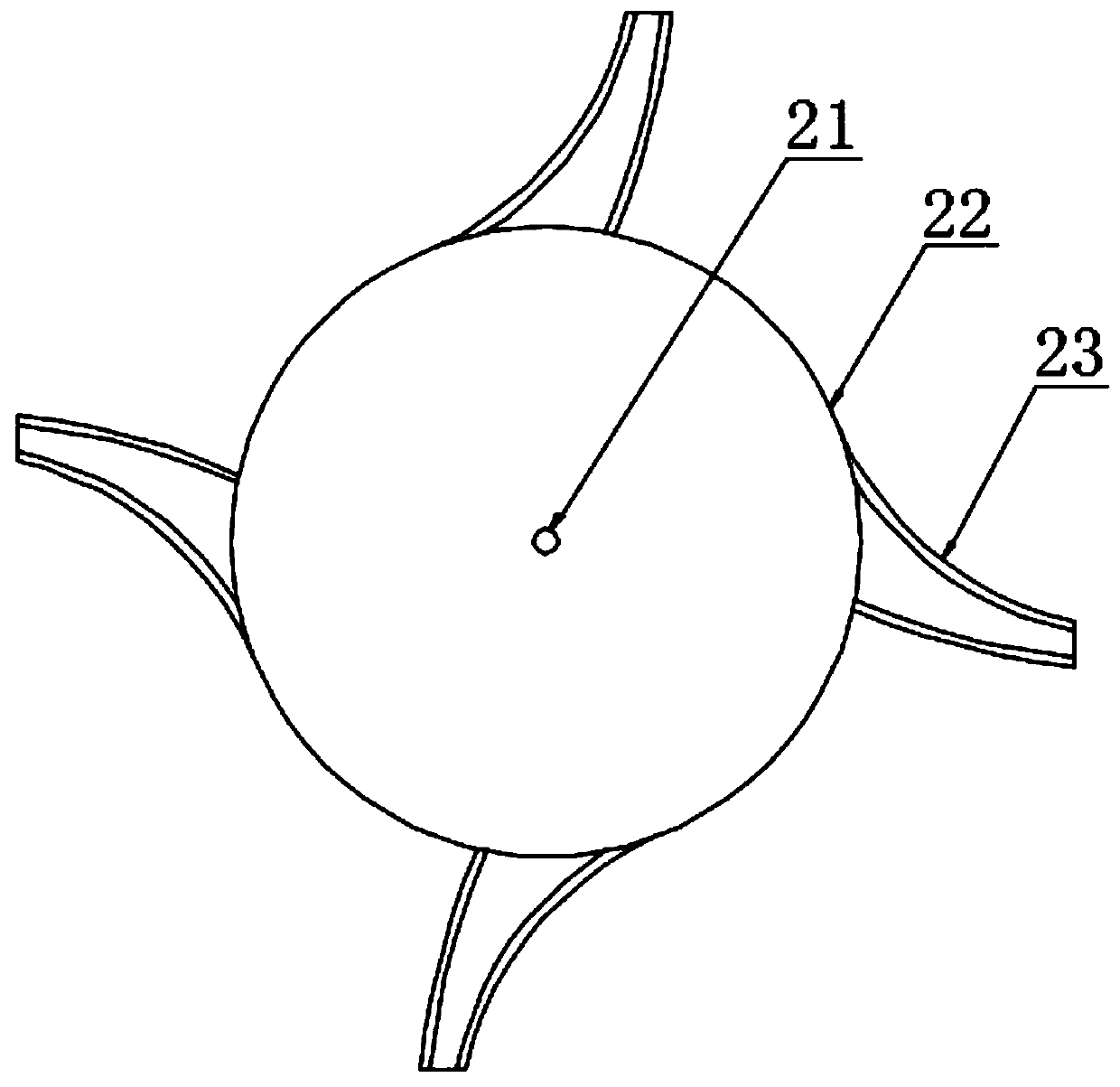
[0036] The water flow regulating mechanism 2 includes a vertical shaft 21, a rotating cylinder 22 and blades 23. The rotating cylinder 22 is fixedly arranged outside the vertical shaft 21. The blades 23 are arranged in multiples and distributed on the outer wall of the rotating cylinder 22 in an annular array. The blades 23 ...
Embodiment 2
[0049] Refer to the attached Figure 5 with Figure 7 , the water flow regulating mechanism 2 also includes a control assembly for controlling the rotational speed of the rotary drum 22, the control assembly includes a geared motor 241, a rotary encoder 242 and a PLC controller 243, and the geared motor 241 is connected to the vertical shaft 21 in transmission, The rotary encoder 242 is fixed on the vertical shaft 21 , and the rotary encoder 242 outputs detection information to the PLC controller 243 , and the PLC controller 243 controls the operation of the reduction motor 241 .
[0050] The implementation scenario is specifically: the present invention can also use the geared motor 241 to control the rotating speed of the rotating cylinder 22 and the blade 23. When in use, the rotary encoder 242 can detect the rotating speed of the vertical shaft 21, and the PLC controller 243 can judge according to the detected rotating speed signal. The speed of the water flow can be prop...
Embodiment 3
[0052] Refer to the attached Figure 6-7 , the adjusting partition 6 is connected to the regulating motor 10 through the rotating shaft 11 for adjusting the flow rate, the rotating shaft 11 runs through the adjusting partition 6, and the top end is fixedly connected with the beam 9 through the bearing and the bracket, and the bottom end is connected with the gate base through the bearing Slot 1 is fixedly connected.
[0053] The implementation scenario is specifically: the present invention can also control and adjust the inclination angle of the partition plate 6 by adjusting the motor 10, thereby controlling the flow rate in the rapid flow area 5; specifically: electrically connect the adjusting motor 10 to the PLC controller 243, and use the rotary encoder After the information detected by 242 judges the water flow velocity, the PLC controller 243 controls the adjustment motor 10 to work, and the adjustment motor 10 drives the adjustment partition 6 to rotate through the ro...
PUM
 Abstract
Description
Claims
Application Information
 - R&D
- Intellectual Property
- Life Sciences
- Materials
- Tech Scout
- Unparalleled Data Quality
- Higher Quality Content
- 60% Fewer Hallucinations
Browse by: Latest US Patents, China's latest patents, Technical Efficacy Thesaurus, Application Domain, Technology Topic, Popular Technical Reports.
© 2025 PatSnap. All rights reserved.Legal|Privacy policy|Modern Slavery Act Transparency Statement|Sitemap|About US| Contact US: help@patsnap.com


