Multifunctional pressure reducing valve in front of meter

A technology of multi-function meter and pressure reducing valve, applied in the direction of functional valve type, lifting valve, valve details, etc., can solve the problems of low applicability, insufficient safety, low practical value, etc., achieve cut-off function safety, and wide application range , the effect of improving safety

Pending Publication Date: 2019-11-05
台州博淼水控设备有限公司
View PDF4 Cites 2 Cited by
  • Summary
  • Abstract
  • Description
  • Claims
  • Application Information

AI Technical Summary

Problems solved by technology

However, it also has some disadvantages: the lower end of the control rod protruding out of the valve body means that anyone can operate it at will, resulting in insufficient security and cannot meet the needs of residential property management or water companies, so the applicability Low, low practical value

Method used


Image

  • Multifunctional pressure reducing valve in front of meter
  • Multifunctional pressure reducing valve in front of meter
  • Multifunctional pressure reducing valve in front of meter

Examples


Embodiment 1

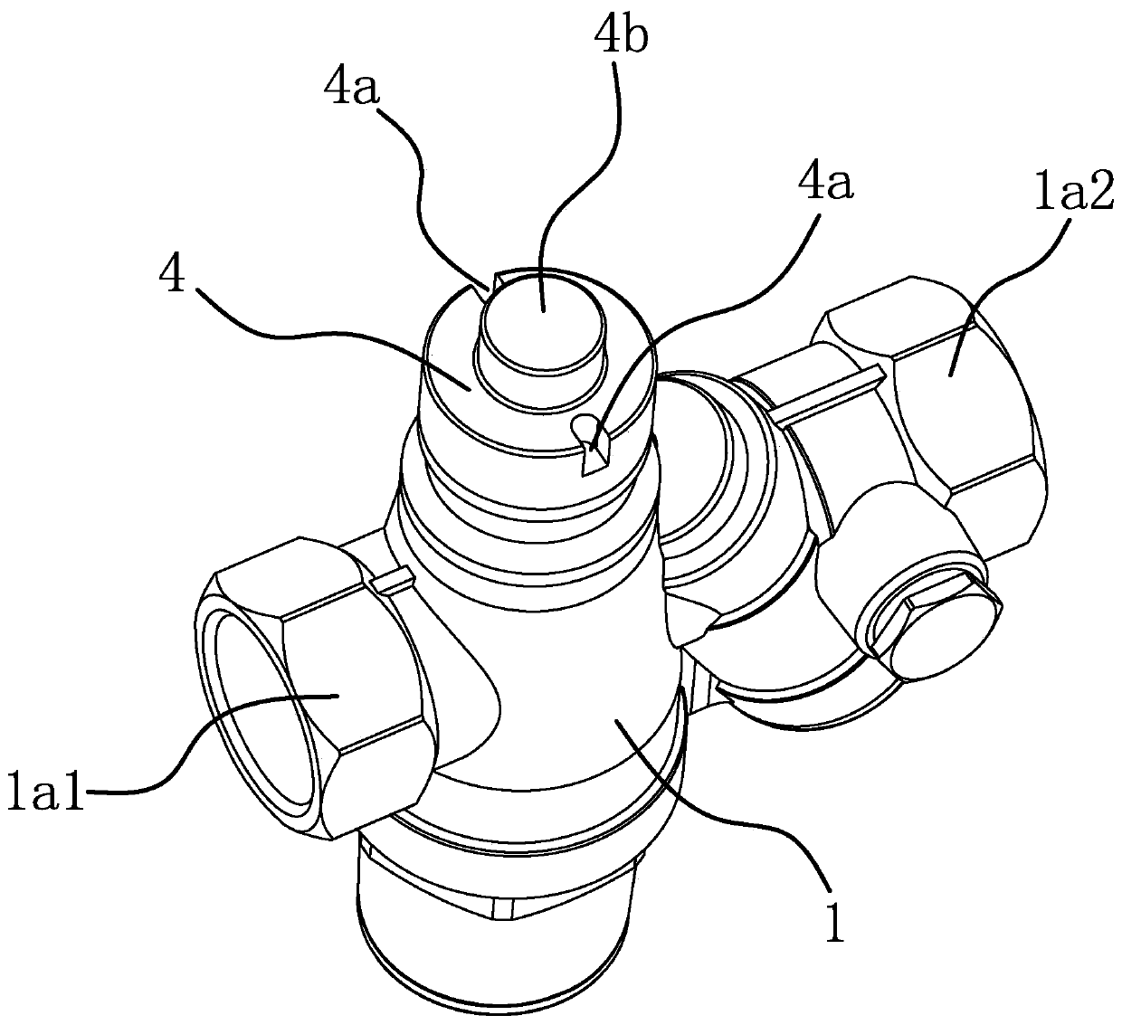
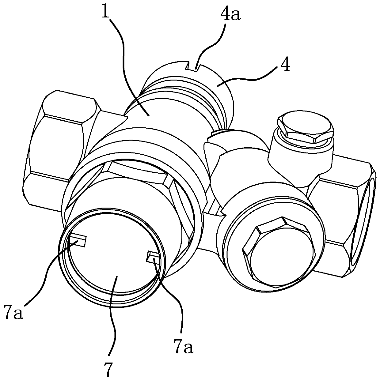
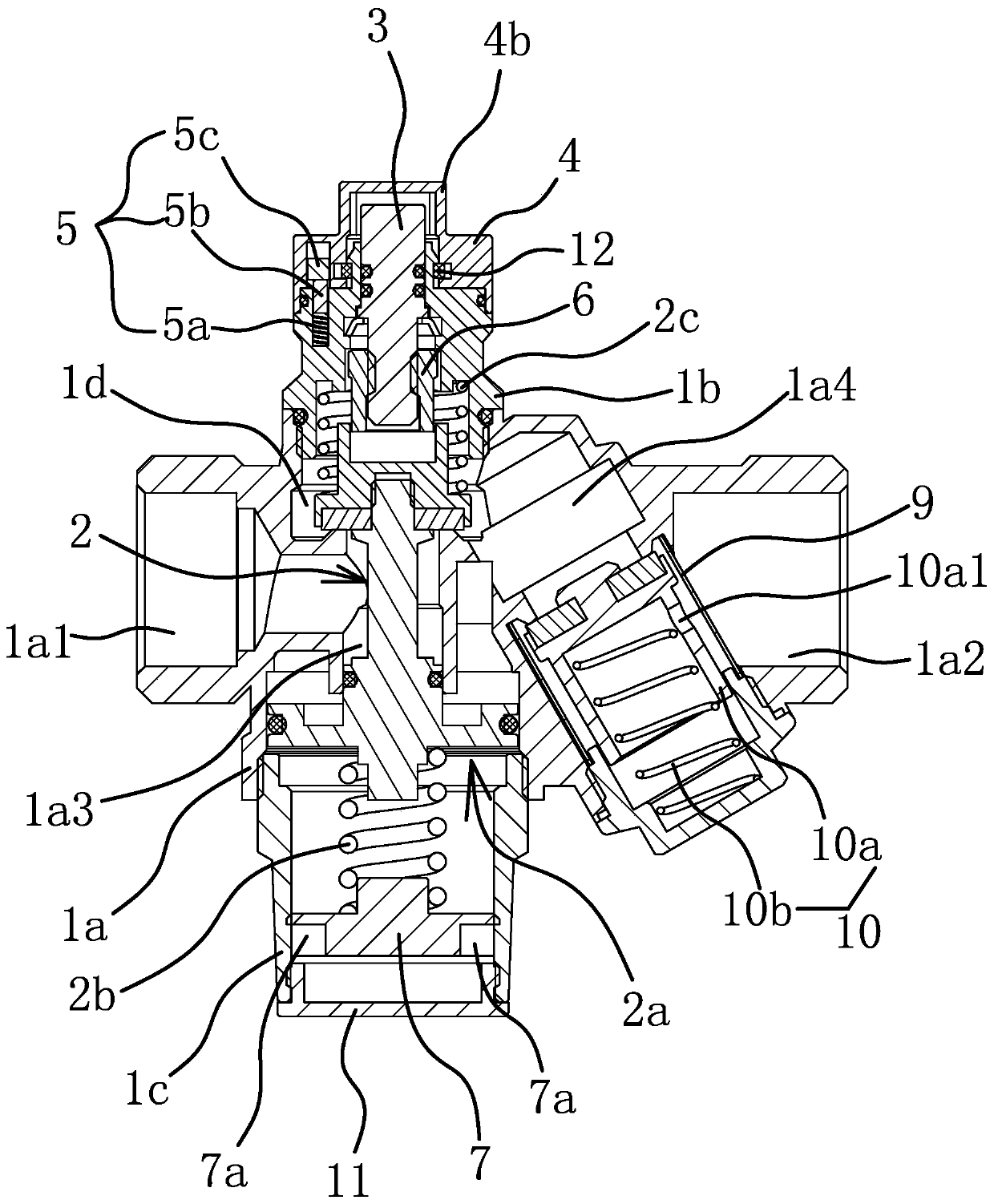
[0039] Such as Figure 1-3 As shown, the pressure reducing valve in front of the multi-function meter includes a valve body 1 whose left and right ends are the water inlet 1a1 and the water outlet 1a2 respectively. The valve body 1 is provided with a water passage 1d, and the water passage 1d is connected with the water outlet 1a2 A water inlet channel 1a3 is arranged vertically in the water passage 1d, the water inlet end 1a1 communicates with the water inlet channel 1a3, and an elastic decompression assembly 2 capable of moving up and down is arranged in the water inlet channel 1a3.

[0040] Such as image 3 and Figure 4 As shown, the elastic decompression assembly 2 includes a decompression core 2a, a decompression spring 2b and a buffer spring 2c. The decompression core 2a includes a core rod 2a1 passing through the water inlet channel 1a3, and a The baffle plate 2a2 and the water retaining head 2a3 fixed on the upper end of the core rod 2a1, the upper end of the core r...

Embodiment 2

[0051] The structure and principle of this embodiment are basically the same as that of Embodiment 1, the difference is that: Figure 7 and Figure 8 As shown, in this embodiment, the end of the water outlet 1a2 is provided with a flaring section 1a21, and the flaring section 1a21 is provided with a control rod and a ball core 13 that can adjust the water flow of the water outlet 1a2. 13 connected, the other end of the control rod stretches out of the flaring section 1a21 and is connected with a handle 14.

[0052]The outlet of the water outlet 1a2 is set as a flaring section 1a21, and a control rod and a ball core 13 are arranged in the flaring section 1a21, so that the user can adjust the flow of the water, that is, the front pressure reducing valve of the multi-function meter is also integrated. Flow adjustment function.


PUM


Abstract

The invention provides a multifunctional pressure reducing valve in front of a meter and belongs to the technical field of valves. The multifunctional pressure reducing valve in front of the meter solves the problem how to improve the use safety under the condition of meeting the cut-off function and the pressure reducing function. The multifunctional pressure reducing valve in front of the metercomprises a valve body and an elastic pressure reducing assembly which is arranged in the valve body and can adjust water outflow pressure. The elastic pressure reducing assembly comprises a pressurereducing core and a pressure reducing spring acting on the pressure reducing core. A rotatable valve rod is arranged in the upper end of the valve body in an inserted manner. The upper end of the valve body is externally provided with a lock nut. A magnetic locking mechanism is arranged between the lock nut and the valve body and enables the lock nut and the valve body to be circumferentially fixed. The valve rod and the valve body are limited axially, and the upper end of the valve rod is circumferentially fixed to the lock nut. The lower end of the valve rod is connected with a pressing sleeve in a threaded manner. The pressing sleeve is circumferentially fixed to the valve body. When the valve rod rotates, the pressing sleeve can push the pressure reducing core to overcome the elastic force of the pressure reducing spring to close the pressure reducing valve. The multifunctional pressure reducing valve in front of the meter well improves the use safety and is wider in application range and more practical.

Description

technical field [0001] The invention belongs to the technical field of valves, and relates to a valve, in particular to a multifunctional meter front pressure reducing valve. Background technique [0002] The essence of the pressure reducing valve is a self-operated pressure difference control device. Its working principle is to reduce the inlet pressure to a certain required outlet pressure, and rely on the energy of the medium itself to keep the outlet pressure automatically stable. The structure of the existing pressure reducing valve is, for example, a pressure reducing valve disclosed in the application number 201320697106.2, which includes a valve body with a water inlet and a water outlet, a valve core seat in the valve body, and a valve disc assembly inside the valve core seat. A bonnet is threaded on the valve body and the bonnet is located above the valve core seat. A pressure regulating assembly is also arranged between the bonnet and the valve core seat, and the ...

Claims


Application Information

Patent Timeline
Patent Type & Authority Applications(China)
IPC IPC(8): F16K17/30F16K35/16F16K1/00F16K1/32F16K1/36F16K5/06F16K31/60B01D35/04
CPCB01D35/046F16K1/00F16K1/32F16K1/36F16K5/06F16K17/30F16K31/60F16K35/16
Inventor 董西伟
Owner 台州博淼水控设备有限公司
Why Eureka
Try Eureka