Quick connector

A fast and fast connection technology, applied in the direction of elbows, pipes/pipe joints/fittings, branch pipelines, etc., can solve the problems of material waste, long installation time, complex structural design of elbow joints and tee joints, etc., to achieve The effect of simple structure operation and convenient installation

Inactive Publication Date: 2019-11-05
浙江埃尔法流体科技有限公司
0 Cites 0 Cited by

AI-Extracted Technical Summary

Problems solved by technology

[0004] The purpose of the present invention is to provide a quick joint, which can solve the "potential danger and safety during use" existing in the prior art; 2. The most common structural design...

Method used

As shown in Figure 10, the general structure of a kind of quick connector provided by the present embodiment is the same as that of Embodiment 1, and the difference is that, in order to facilitate positioning, a downward The extended limiting convex strip 17 is provided with a fixing groove 18 that cooperates with the limiting convex strip 17 on the extending convex edge 13 of the lower half of the housing 7. By setting the limiting convex strip 17 to cooperate with the fixing groove 18, it is convenient for installation when positioning.
As shown in Figure 11, the general structure of a kind of quick connector provided by this embodiment is the same as that of Embodiment 1, and the difference is that, in order to improve the anti-slip limiting effect, the inner wall of the sealing cylinder 4 is provided with an inclined reinforcement The ribs 19 can provide an overall anti-slip effect during installation by providing the reinforcing ribs 19 .
As shown in Figure 9, the general structure of a kind of quick connector provided by this embodiment is the same as that of Embodiment 1, and the difference is that, in order to improve the fixing effect, outside the sealing cylinder 4, relative to the upper half housing 6 and the lower Sealing protruding strips 16 are provided at the joint gaps of the half casings 7 , and the sealing effect can be further improved by arranging the sealing protruding strips 16 .
In the present embodiment, preferably, in order to facilitate the connection at the bend, the shell 1 and the sealing cylinder 4 are in the form of an elbow, and during installation, this structure can be adapted to be installed on the compressed air supply source for It is applied to the place where the pipe is to be disassembled and assembled. The quick installation method is as follows. First, the two sides of the upper half of the shell 6 and the lower half of the shell 7 are raised at the corresponding positions by a special protruding machine. The flange of the ring extends the convex edge 13, and then inserts the connecting pipe body parts that need to be installed on both sides into the sealing ring 2, and then places the semicircular grooves 8 on both sides of the upper half shell 6 and the lower half shell 7 in the sealing ring. The two sides of the ring 2 are spliced ...

Abstract

The invention discloses a quick connector. The quick connector comprises a shell and a sealing ring; the shell comprise two or more connection ports; the sealing ring comprises a sealing barrel body and sealing outlets, and each sealing outlet is located in the corresponding connection port; the shell further comprises an upper half shell body and a lower half shell body, and the upper half shellbody and the lower half shell body are each provided with a semi-circular groove; the upper half shell body is provided with first semi-circular notches which are the same with the connection ports inquantity and upper portion distribution position; the lower half shell body is provided with second semi-circular notches; each first semi-circular notch and the corresponding second semi-circular notch form the integrated connection port after being matched; each connection port is internally provided with a positioning concave ring used for installing a flange on the outer side of a connectionpipe body; extending convex edges extending outwards are arranged in side edges, opposite to the semi-circular grooves, of the upper half shell body and the lower half shell body; and the extending convex edges of the upper half shell body and the lower half shell body are locked and fixed through two or more bolts after being attached to each other. The quick connector is simple in structure, easy to operate and relatively convenient to install.

Application Domain

Technology Topic

Image

  • Quick connector
  • Quick connector
  • Quick connector

Examples

  • Experimental program(7)

Example Embodiment

[0031] Example 1:
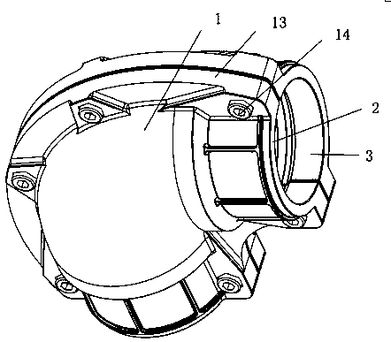
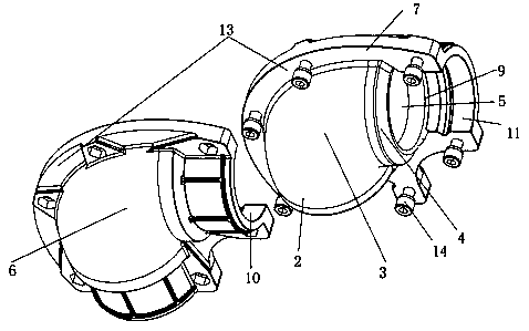
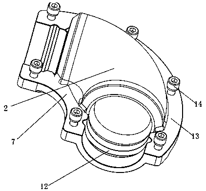
[0032] like Figure 1-4 As shown, a quick connector provided in this embodiment includes a casing 1 with an assembly channel and a sealing ring 2, the casing 1 includes more than two connection ports 3, the sealing ring 2 includes a sealing cylinder 4 and There are 3 sealed outlets 5 with the same number as the connection ports, and each sealed outlet 5 is located in the connection port 3. The shell 1 also includes an upper half shell 6 and a lower half shell 7 that can be assembled and disassembled. Half shell 6 and lower half shell 7 are all provided with a semicircular groove 8, and the breach on the semicircular groove 8 on the upper half shell 6 and the lower half shell 7 is combined mutually and constitutes for Install the position-limiting pipeline 9 of the sealing cylinder 4, be provided with the first semicircular notch 10 that is identical with the number of connection ports 3 and the distribution position of the connection port 3 tops on the upper half housing 6, and set on the lower half housing 7 There is a second semicircular notch 11 which has the same number as the number of connecting ports and the distribution position of the lower part of the connecting port 3, and a corresponding first semicircular notch 10 and second semicircular notch 11 cooperate to form a complete connecting port 3. There is a positioning concave ring 12 for installing the outer flange of the connecting pipe body in each connecting port 3, and the corresponding connecting pipe body part extends into the sealing cylinder 4, and the upper half shell 6 and the lower half shell The body 7 is provided with an outwardly extending extension lip 13 relative to the side of the semicircular groove 8, and the extension lip 13 of the upper half shell 6 and the lower half shell 7 is fitted together and passed through more than two Bolt 14 is locked and fixed.
[0033] In this embodiment, as a preference, in order to facilitate the connection at the bend, the outer shell 1 and the sealing cylinder 4 are in the form of an elbow. During installation, this structure can be suitable for being installed on the compressed air supply source corresponding to the bend. The place where the pipe is bent, and the pipe fittings can be disassembled for assembly. The quick installation method is as follows. First, use a special convex pipe machine to protrude a circle of flanges on both sides of the upper half of the shell 6 and the lower half of the shell 7 at the corresponding positions. That is, extend the convex edge 13, then insert the connecting pipe body parts that need to be installed on both sides into the sealing ring 2, and then place the semicircular grooves 8 on both sides of the upper half shell 6 and the lower half shell 7 in the sealing ring 2 The two sides are spliced ​​to form the limiting pipe 9 of the sealing ring 2. At the same time, the two sides of the upper half shell 6 and the lower half shell 7 are aligned, the two pieces are closed, and the bolt 14 is tightened. The bolt 14 is a hexagon socket bolt, which finally improves the speed The safety of the joint during use reduces the installation time and materials. At the same time, the connection port 3 on both sides is provided with a positioning concave ring 12 for installing the outer flange of the connecting pipe body, so as to realize the positioning effect on the outer side of the connecting tank body and avoid The problem of air leakage, at the same time, if the structure does not need to be installed at the elbow position, the entire quick joint can be set as a linear structure, that is, the bending part will not be bent. When installing, first use a special convex pipe machine to put it on The two sides of the half shell 6 and the lower half shell 7 protrude a circle of flanges at the corresponding positions, that is, extend the flange 13, and then insert the connecting pipe body parts that need to be installed on both sides into the sealing ring 2, and then insert the upper half The semicircular grooves 8 on both sides of the housing 6 and the lower half of the housing 7 are placed on both sides of the sealing ring 2 and spliced ​​to form the limit pipe 9 of the sealing ring 2, and the upper half of the housing 6 and the lower half of the housing 7 are placed on both sides Align, close the two pieces, tighten the bolt 14, the bolt 14 is a hexagon socket bolt, through the design of the above structure, the connecting pipe body on both sides is connected with the sealing ring first, and then the shell 1 of the outer detachable assembly channel is used to carry out Fixed, so that when the interior is ventilated, due to the function of the sealing ring 2 and the outer shell 1, there will be no problem of being washed out by the compressed air, and the sealing ring 2 is used to seal the connection first, and then the outer shell is used for double fixing, and finally it can be effectively It avoids the dangerous problem caused by the loosening of the pipe fittings and the compressed air is sprayed out. At the same time, the overall structure is simple to operate and relatively convenient to install.

Example Embodiment

[0034] Example 2:
[0035] like Figure 5As shown, the general structure of a quick connector provided in this embodiment is the same as that of Embodiment 1, the difference is that, as a preference, in order to facilitate the three-channel connection, the outer shell 1 and the sealing cylinder 4 are in the form of a three-way pipe , that is, the outer shell and the inner sealing cylinder 4 are set in the form of a tee. When installing, first use a special convex tube machine to protrude a ring of flanges on both sides of the upper half of the shell 6 and the lower half of the shell 7 at the corresponding positions. Extend the convex edge 13, and then insert the connecting pipe body part that needs to be installed on the three sides into the sealing ring 2, and then place the semicircular grooves 8 on both sides of the upper half shell 6 and the lower half shell 7 in the sealing ring 2 The two sides are spliced ​​together to form the limit pipe 9 of the seal ring 2. At the same time, the two sides of the upper half shell 6 and the lower half shell 7 are aligned, the two pieces are closed, and the bolt 14 is tightened. The bolt 14 is a hexagon socket bolt. Through the design of the above structure , so that the connecting pipes on both sides are connected with the sealing ring first, and then fixed by the shell 1 of the detachable assembly channel on the outside, so that when the inside is ventilated, due to the role of the sealing ring 2 and the outer shell 1, there will be no The problem of being washed out by the compressed air, and firstly use the sealing ring 2 to seal the connection, and then use the outer shell for double fixing, and finally can effectively avoid the problem that the pipe fittings are loose and cause the compressed air to be ejected and cause danger. At the same time, the overall structure is easy to operate and easy to install. It is also relatively convenient.

Example Embodiment

[0036] Example 3:
[0037] like Figure 6-8 As shown, the general structure of a quick connector provided in this embodiment is the same as that in Embodiment 1, the difference is that, as a preference, in order to improve the position-limiting effect, a position-limiting protruding ring 15 is provided on the outer wall of the sealing outlet 5, and the The sealing outlet 5 cooperates with the position-limiting convex ring 15 to form a hook structure 21, and the structural structures 21 on both sides cooperate with the half-side inclined steps 22 provided on the corresponding side of the semicircular groove 8, and the upper half of the housing 6 and the lower half After the two sides of the housing 7 are aligned, the two half-side inclined steps 22 on the same side cooperate with each other to form a limiting step surface 23 for clamping the hook structure 21 .
[0038] By setting the limit protruding ring 15 and the setting of the hook structure 21, and using the limit step surface 23, after the installation is completed, the entire sealing ring 2 is firmly locked in the limit pipe 9 by the limit step surface 23, In the end, it will not come out from the position-limiting pipe 9, and it can finally play the role of position-limiting during installation, so that the internal gas will not be eliminated after use, and the problem of gas outlet due to the detachment of the entire component.

PUM

no PUM

Description & Claims & Application Information

We can also present the details of the Description, Claims and Application information to help users get a comprehensive understanding of the technical details of the patent, such as background art, summary of invention, brief description of drawings, description of embodiments, and other original content. On the other hand, users can also determine the specific scope of protection of the technology through the list of claims; as well as understand the changes in the life cycle of the technology with the presentation of the patent timeline. Login to view more.

Similar technology patents

Locking structure and paper box for printing on POS machine without buckle hand

PendingCN108086826ASimple structure and operationWing fastenersEngineeringMechanical engineering
Owner:SHENZHEN XINGUODU PAYMENT TECH CO LTD

Multifunctional electric vehicle charger

InactiveCN112290625ASimple structure and operationGood human-computer interfaceCircuit monitoring/indicationCharging stationsAutomotive engineeringElectric vehicle
Owner:天长市绿普尔电子有限公司

Classification and recommendation of technical efficacy words

  • Simple structure and operation
  • Easy to install

Rotary type vehicle carrying board one-position for two-car parking device

InactiveCN101033653AReduce channel areaSimple structure and operationParkingsElectric machineryVehicle frame
Owner:朱建华

Overturn-preventing falling-preventing attached lifting scaffold

InactiveCN105401715ASimple structure and operationBuilding support scaffoldsEngineeringSelf weight
Owner:ZHONGYIFENG CONSTR GRP

Puncture needle positioning device

ActiveCN106852702AImprove efficiency and accuracySimple structure and operationDiagnosticsSurgical needlesNeedle positionSurgery
Owner:METAL INDS RES & DEV CENT +1

Organic vacuum evaporation source

PendingCN106987809ASimple structure and operationEasy to produceVacuum evaporation coatingSputtering coatingPhysicsThermocouple Wire
Owner:DALIAN JIAOTONG UNIVERSITY

Ultrasound guidance system

InactiveUS20070073155A1Easy to installAccurate and simple needle placementUltrasonic/sonic/infrasonic diagnosticsSurgical needlesUltrasound guidanceNeedle guidance
Owner:ULTRASOUND VENTURES

Power train for small recreational vehicle

InactiveUS20050173180A1Easy to installRace vehiclesUnderstructuresTransaxleAutomotive engineering
Owner:TECUMSEH PROD CO
Why Eureka
Try Eureka