Contact signal collection circuit for online verifying gas density relay on spot

A density relay and signal acquisition technology, applied in the electric power field, can solve problems such as potential safety hazards, hazards, flashovers, etc., and achieve the effect of ensuring safety

Pending Publication Date: 2019-11-05
SHANGHAI ROYE ELECTRICAL CO LTD
View PDF0 Cites 4 Cited by
  • Summary
  • Abstract
  • Description
  • Claims
  • Application Information

AI Technical Summary

Problems solved by technology

3) When the temperature drops, too much moisture may form condensation water, which will significantly reduce the insulation strength of the surface of the insulating part, or even flashover, causing serious damage
In addition, if the on-site inspection of the inspectors is not performed in a standardized manner, there are still potential safety hazards

Method used


Image

  • Contact signal collection circuit for online verifying gas density relay on spot
  • Contact signal collection circuit for online verifying gas density relay on spot
  • Contact signal collection circuit for online verifying gas density relay on spot

Examples


Embodiment 1

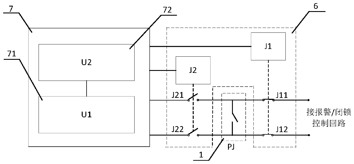
[0058] figure 1 It is a control circuit schematic diagram of a contact signal acquisition circuit (collector) 6 used for on-site on-line calibration of gas density relays for high-voltage electrical equipment. Such as figure 1 As shown, the contact signal acquisition circuit (collector) is connected together with the gas density relay 1 and the online verification device 7 on the electrical equipment. The contact signal acquisition circuit (collector) 6 of this embodiment includes a first relay J1 and a second relay J2. The first relay J1 is provided with normally closed contacts J11 and J12, and the normally closed contacts J11 and J12 are connected in series in the contact signal control loop; the second relay J2 is provided with normally open contacts J21 and J22, and the normally open contacts J21 and J22 are provided. Contacts J21 and J22 are connected to contact P of gas density relay 1 J It is also possible that the first relay J1 and the second relay J2 are integrat...

Embodiment 2

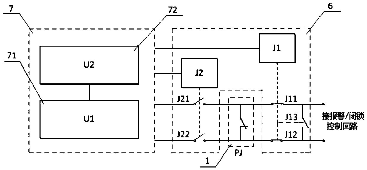
[0066] Such as figure 2 As shown, the difference between the present embodiment and the first embodiment is that a normally open contact J13 is added between the normally closed contacts J11 and J12. In the non-calibration state, the contact P J It is a normally closed density relay, the normally closed contacts J11 and J12 are closed, while J13 is open, and the normally open contacts J21 and J22 are open. In the verification state, the normally open contact J13 of the contact signal acquisition circuit (collector) 6 closes the contact signal control loop, while the normally closed contacts J11 and J12 are disconnected, that is, the contact P of the gas density relay 1 is cut off. J Connection with the contact signal control circuit; at the same time, the normally open contacts J21 and J22 are closed or automatically closed under the control of the online verification device 7, and the contact P of the gas density relay 1 J The normally open contacts J21 and J22 of the seco...

Embodiment 3

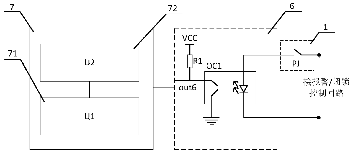
[0068] Such as image 3 As shown, the contact signal acquisition circuit (gatherer) 6 of the present embodiment includes a photocoupler OC1 and a resistor R1, and the photocoupler OC1 includes a light emitting diode and a phototransistor; the anode of the light emitting diode and the Contact P of gas density relay 1 J Form a closed loop in series; the emitter of the phototransistor is grounded; the collector of the phototransistor is connected to the on-line verification device 7 as the output terminal out6 of the signal acquisition circuit (gatherer) 6, and the phototransistor The collector is also connected to the power supply through the resistor R1.

[0069] Through the above circuit, the contact P of the gas density relay 1 can be easily known through the high and low levels output by the output terminal out6 of the contact signal acquisition circuit (collector) 6. J is open or closed. Specifically, when the joint P J When closed, the closed circuit is energized, the ...


PUM


Abstract

The invention provides a contact signal collection circuit for online verifying a gas density relay on spot. The contact signal collection circuit comprises a first collecting circuit and a second collecting circuit, wherein the first connecting circuit connects a contact of the gas density relay and a contact signal control loop, and the second connecting circuit connects the contact of the gas density relay and a contact signal sampling port of an online verification device; when the contact signal collection circuit is in a non-verification state, the second connecting circuit is opened, and the first connecting circuit is closed; when the contact signal collection circuit is in a verification state, the first connecting circuit is opened, and connected with the second connecting circuit, then the contact of the gas density relay and the contact signal sampling port of the online verification device are connected, and it is ensured that during verification, contact actuating signalsare not uploaded, and the safety operation of a power grid is not influenced; meanwhile, the gas density relay is free of maintenance, the benefit is greatly increased, and operation reliability andsafety of the power grid are greatly improved.

Description

technical field [0001] The invention relates to the field of electric power technology, in particular to a contact signal acquisition circuit (collector) used in high-voltage electrical equipment for on-site calibration of gas density relays. Background technique [0002] Gas density relay is generally used to monitor and control the density of insulating gas in high-voltage and medium-voltage electrical equipment. It is equipped with a contact signal control circuit inside. When a gas leak occurs, the contact of the gas density relay will act to generate a contact signal, and the contact signal control circuit will send an alarm or block according to the contact signal, so as to realize the safe operation protection of electrical equipment. [0003] At present, SF6 (sulfur hexafluoride) electrical equipment has been widely used in the power sector and industrial and mining enterprises, which has promoted the rapid development of the power industry. In recent years, with th...

Claims


Application Information

Patent Timeline
Patent Type & Authority Applications(China)
IPC IPC(8): G01N9/00G01D21/02G01R31/327G05B19/04H01H35/26
CPCG01N9/00G01D21/02G05B19/04G01R31/3272G01R31/3274G01R31/3271H01H35/26G05B19/042H01H33/563H01H47/002H01H35/24
Inventor 曾伟常敏黄小泵廖海明金海生王恩林
Owner SHANGHAI ROYE ELECTRICAL CO LTD
Why Eureka
Try Eureka