Multifunctional gas density relay

A technology of gas density and relay, applied in the field of electric power, can solve problems such as potential safety hazards, flashovers, and hazards

Pending Publication Date: 2019-11-05
SHANGHAI ROYE ELECTRICAL CO LTD
View PDF0 Cites 4 Cited by
  • Summary
  • Abstract
  • Description
  • Claims
  • Application Information

AI Technical Summary

Problems solved by technology

3) When the temperature drops, too much moisture may form condensation water, which will significantly reduce the insulation strength of the surface of the insulating part, or e

Method used


Image

  • Multifunctional gas density relay
  • Multifunctional gas density relay
  • Multifunctional gas density relay

Examples


Embodiment 1

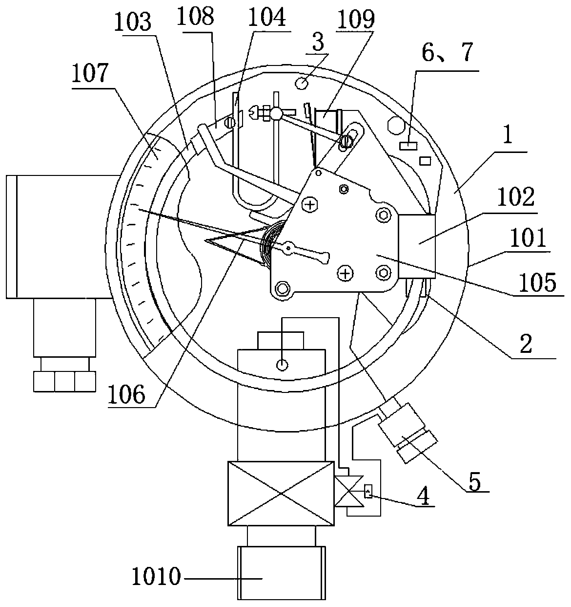
[0113] figure 1 It is a schematic structural diagram of a multifunctional gas density relay according to an embodiment of the present invention. Such as figure 1 As shown, a multifunctional gas density relay 1 includes a housing 101, and a base 102, an end seat 108, a pressure detector 103, a temperature compensation element 104, and several signal generators 109 arranged in the housing 101 , movement 105, pointer 106, dial 107 and equipment connection joint 1010. The gas density relay 1 communicates with electrical equipment through the equipment connection joint 1010, one end of the pressure detector 103 is fixed on the base 102 and communicates with it, and the other end of the pressure detector 103 passes through The end seat 108 is connected to one end of the temperature compensation element 104, and the other end of the temperature compensation element 104 is provided with a crossbeam, and the crossbeam is provided with a pusher to push the signal generator 109 to make...

Embodiment 2

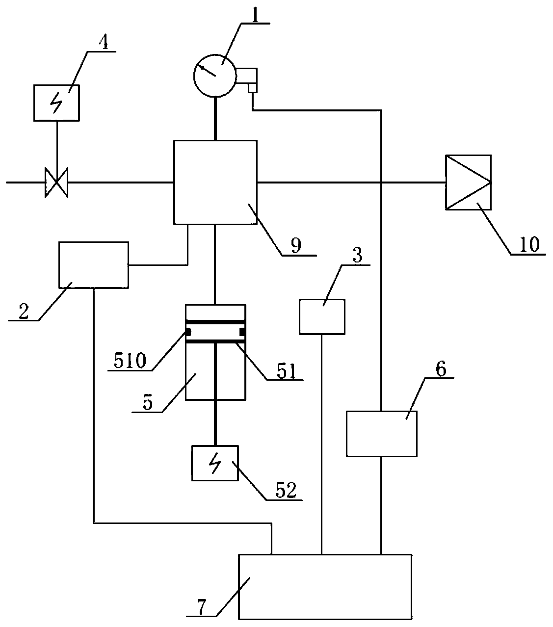
[0118] figure 2 It is a structural schematic diagram of a multifunctional gas density relay. Such as figure 2 As shown, in addition to the housing 101, as well as the base 102, end seat 108, pressure detector 103, temperature compensating element 104, several signal generators 109, movement 105, pointer 106, scale Disk 107 and equipment connection joint 1010 also include: pressure sensor 2, temperature sensor 3, valve 4, pressure adjustment mechanism 5, online verification contact signal sampling unit 6, intelligent control unit 7, multi-way joint 9 and air supply interface 10 . The valve 4 , the pressure sensor 2 , the pressure regulating mechanism 5 and the air supply interface 10 are arranged on the multi-way joint 9 . Specifically, the air inlet of the valve 4 is provided with an interface that communicates with the electrical equipment, and its air inlet is sealed and connected to the electrical equipment, and communicates with the air chamber of the electrical equip...

Embodiment 3

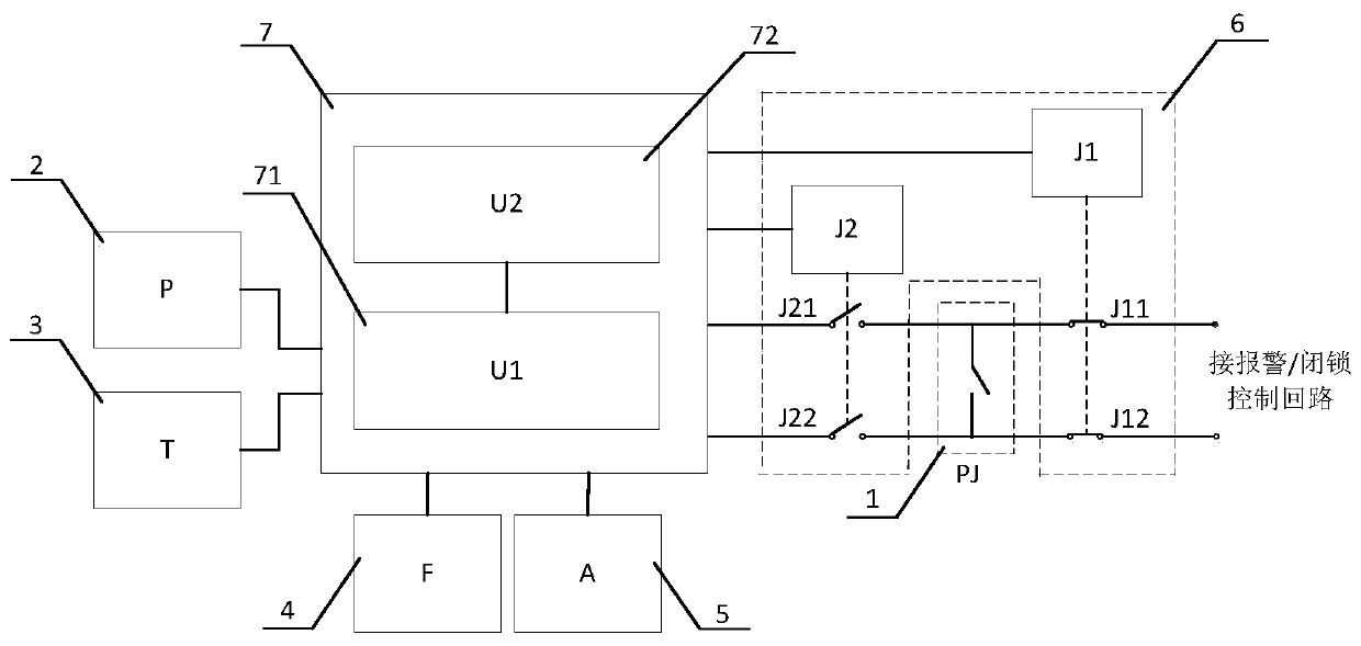
[0129] image 3 It is a schematic diagram of the control circuit of a multifunctional gas density relay. Such as image 3 As shown, the online verification contact signal sampling unit 6 of this embodiment is provided with a protection circuit, including a first connection circuit and a second connection circuit, and the first connection circuit is connected to the contacts of the gas density relay 1 (signal generator ) and a contact signal control circuit, the second connecting circuit connects the contact of the gas density relay 1 with the intelligent control unit 7, and in the non-verification state, the second connecting circuit is disconnected, and the first The connection circuit is closed; in the verification state, the online verification contact signal sampling unit 6 cuts off the first connection circuit, connects the second connection circuit, and connects the contact of the gas density relay 1 with the intelligent control Unit 7 is connected.

[0130] Specifica...


PUM


Abstract

The invention provides a multifunctional gas density relay. The relay comprises a casing body, a base arranged in the casing body, a pressure detector, a temperature compensating element, at least onesignal generator, a device connector connected with electrical equipment, and an online verification contact signal sampling unit. The online verification contact signal sampling unit is connected with the signal generator and used for sampling a contact signal generated when the multifunctional gas density relay generates a contact action at a sampling ambient temperature. The online verification contact signal sampling unit is relatively isolated from the contact of the multifunctional gas density relay on a circuit in a non-verification state. In a verification state, a contact signal control loop is cut off to ensure that the contact signal of the multifunctional gas density relay is not uploaded and safe operation of a power grid is not affected.

Description

technical field [0001] The invention relates to the field of electric power technology, in particular to a multifunctional gas density relay applied to high-voltage and medium-voltage electrical equipment. Background technique [0002] Gas density relay is generally used to monitor and control the density of insulating gas in high-voltage and medium-voltage electrical equipment. It is equipped with a contact signal control circuit inside. When a gas leak occurs, the contact of the gas density relay will act to generate a contact signal, and the contact signal control circuit will send an alarm or block according to the contact signal, so as to realize the safe operation protection of electrical equipment. [0003] At present, SF6 (sulfur hexafluoride) electrical equipment has been widely used in the power sector and industrial and mining enterprises, which has promoted the rapid development of the power industry. In recent years, with the rapid economic development, the cap...

Claims


Application Information

Patent Timeline
IPC IPC(8): H01H35/26H01H35/32H01H35/36G01N9/26G01K15/00G01L27/00
CPCG01K15/005G01L27/005G01N9/266H01H35/26H01H35/32H01H35/36
Inventor 常敏郭正操王乐乐曾伟廖海明张元昊
Owner SHANGHAI ROYE ELECTRICAL CO LTD
Why Eureka
Try Eureka