ATM communication apparatus

A technology of communication equipment and cell, applied in transmission systems, digital transmission systems, time-division multiplexing selection devices, etc., can solve problems such as long delays, long delays, and low transmission efficiency, and achieve the effect of improving utilization

Inactive Publication Date: 2003-03-26
RENESAS ELECTRONICS CORP
View PDF2 Cites 0 Cited by
  • Summary
  • Abstract
  • Description
  • Claims
  • Application Information

AI Technical Summary

Problems solved by technology

[0019] The first problem is: the host bus (see figure 1 Reference number 4) in the transmission efficiency is very low
In this case, as the PCI bus between the ATM communication device and the host memory becomes more congested, the bus access time is longer, or the delay in receiving the payload data from the host memory is greater, the first problem will be more serious. obvious
[0022] The second problem is that there is a long delay between the confirmation of cell transmissio...

Method used


Image

  • ATM communication apparatus
  • ATM communication apparatus
  • ATM communication apparatus

Examples


Embodiment Construction

[0065] Various embodiments of the present invention will be described in detail below with reference to the accompanying drawings.

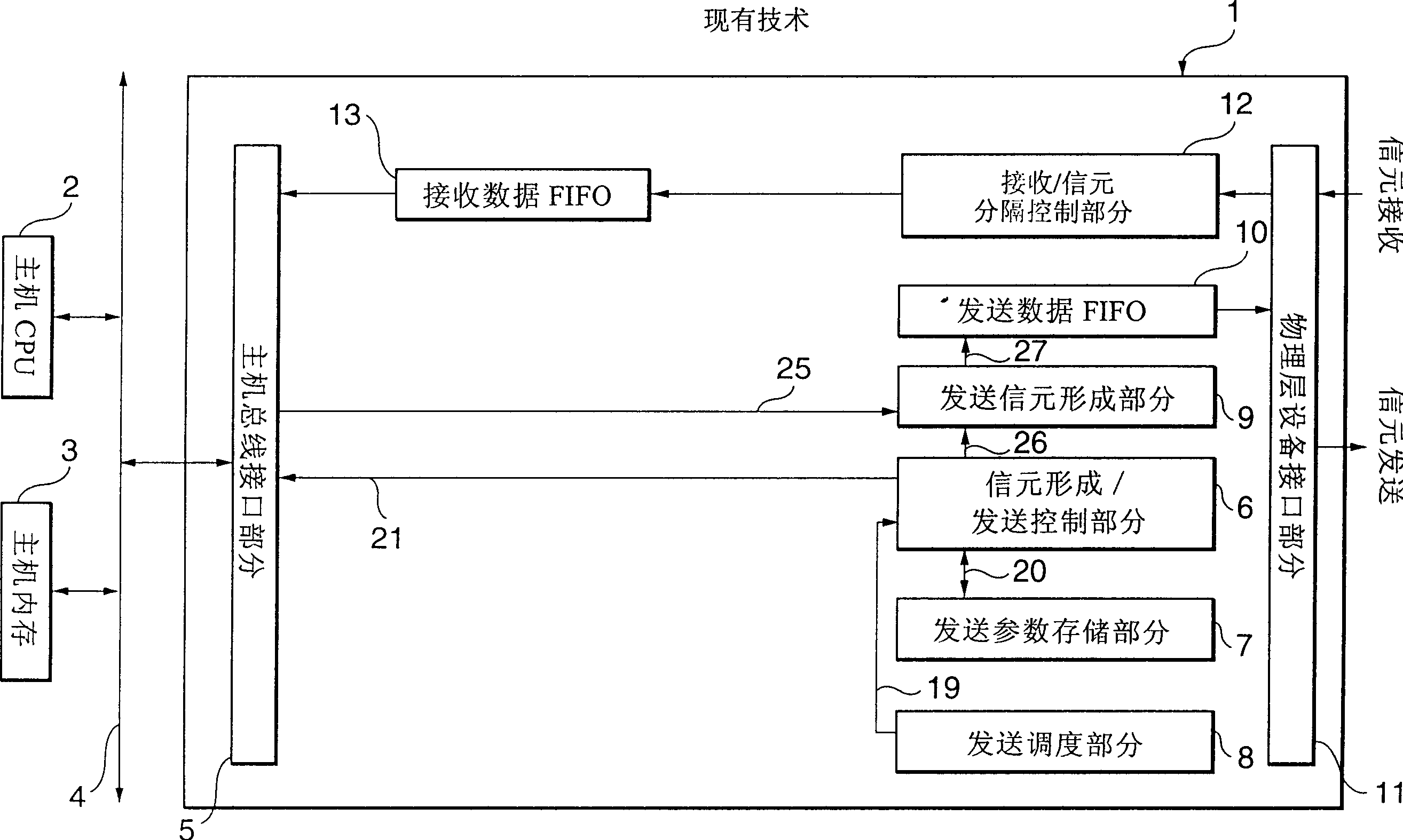
[0066] Figure 4 It is a schematic structural diagram of the ATM communication device according to the first embodiment of the present invention.

[0067] Such as Figure 4 shown, with reference to figure 1 Similar to the description of conventional ATM communication equipment (prior art), a kind of ATM communication equipment 1 according to the first embodiment of the present invention has an ATM cell forming / sending part, which consists of a sending scheduling part 8, a signal A cell formation / transmission control section 6, a transmission parameter storage section 7, a transmission cell formation section 9, and a transmission data FIFO 10 are constituted. The reception / separation part of this ATM communication equipment 1 is divided into control part 12 by receiving / cell, receives data FIFO13, is used to send / receive data to / from host bus i...


PUM


Abstract

In an ATM communication apparatus, when a transmission schedule section determines a transmission virtual channel, payload data corresponding to a plurality of cells is read out from a host memory if no payload for the virtual channel is present in a transmission payload temporarily storing section. The payload corresponding to a first cell, a corresponding cell header, and a corresponding cell trailer are formed into a transmission cell. The cell is transmitted to a physical layer device. Payloads corresponding to the second and subsequent cells are temporarily stored in the transmission payload temporarily storing section.

Description

technical field [0001] The invention relates to an ATM communication device. More specifically, the ATM communication equipment involved in the present invention has a transmission data temporary storage circuit that can be used for each virtual channel (hereinafter referred to as VC). Background technique [0002] figure 1 The block diagram of shows a traditional ATM communication equipment. Such as figure 1 Shown, the ATM cell of conventional ATM communication equipment 1 forms / sends part and is made up of following each part: sends scheduling part 8, and it is used for selecting the VC that will send next; Cell forms / sends control part 6, and it uses To receive the information of selecting VC from the transmission scheduling part 8 and control the VC cell transmission; the transmission parameter storage part 7, which can store the information (transmission parameters) used to control the transmission of the cell; be used to form a transmission of the cell a transmit c...

Claims


Application Information

Patent Timeline
IPC IPC(8): H04L69/14H04L47/22H04L47/43H04L49/901H04Q3/00H04Q11/04
CPCH04L2012/5652H04L2012/5616H04L2012/5679H04Q11/0478
Inventor 片柳智志
Owner RENESAS ELECTRONICS CORP
Why Eureka
Try Eureka