Annular tension elastic rib deployable antenna structure
An antenna structure and elasticity technology, applied in antennas, electrical components and other directions, can solve the problems of difficult to put into practice in the field of large-diameter high-precision cable-net antennas, the difficulty of optimizing design and tension array adjustment and control, to simplify the adjustment work, Achieving the effect of weight reduction and improved surface accuracy
- Summary
- Abstract
- Description
- Claims
- Application Information
AI Technical Summary
Problems solved by technology
Method used
Image

Examples
Embodiment 1
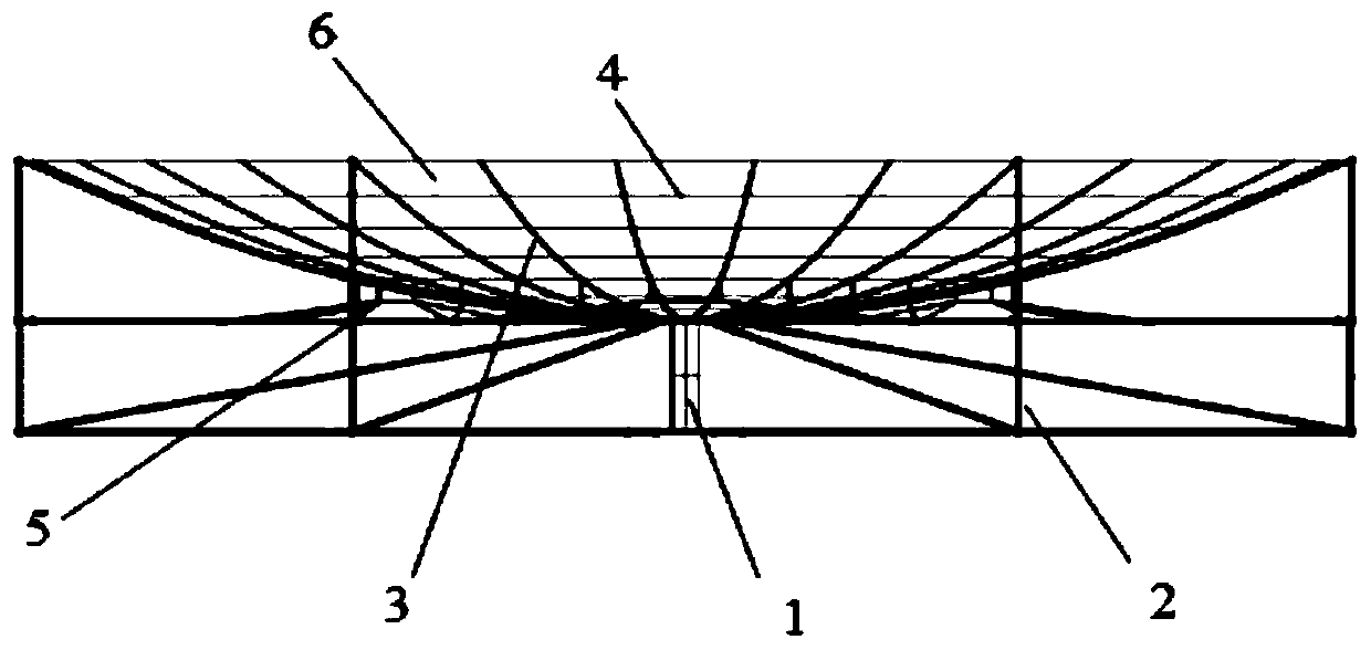
[0080] A hoop tension elastic rib 3 deployable antenna structure, its structure see Figure 1-Figure 5 shown, including:
[0081] Center faceplate node 1;
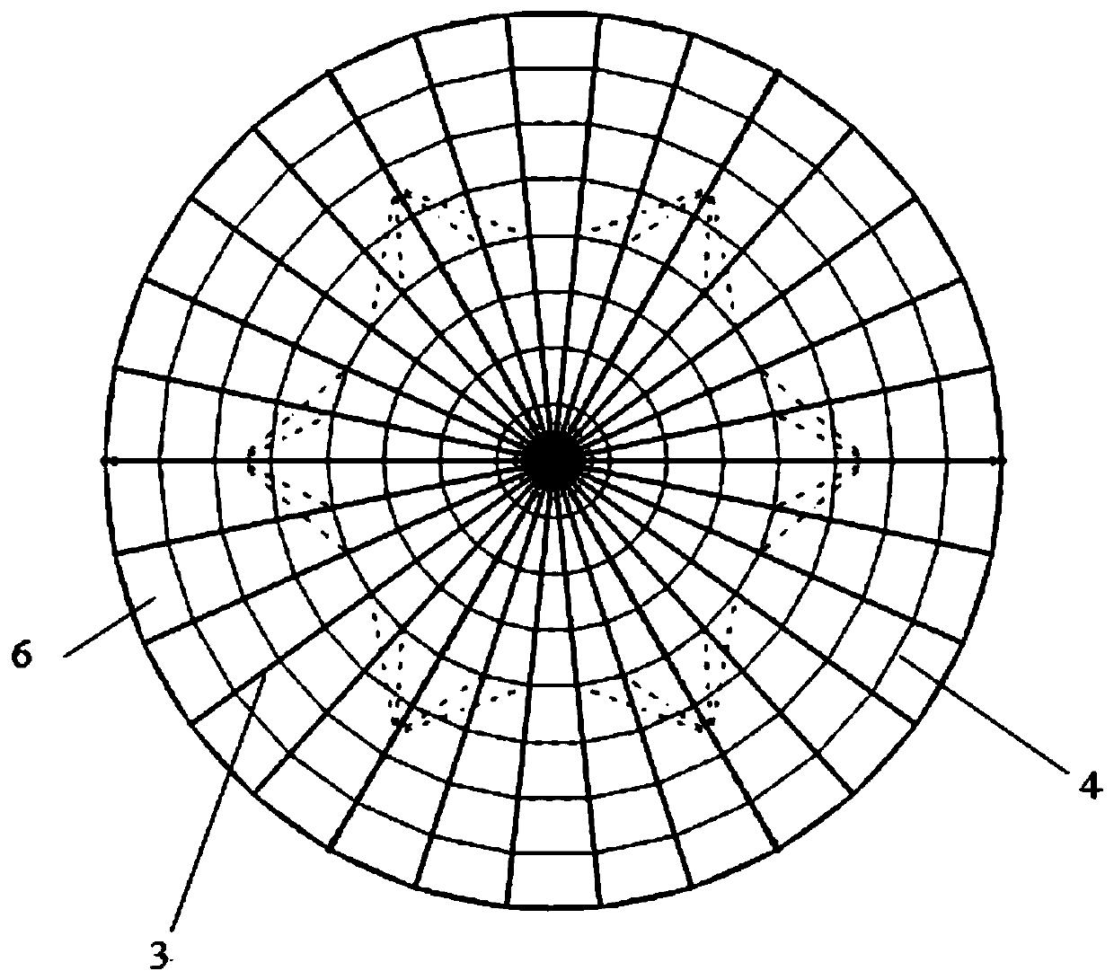
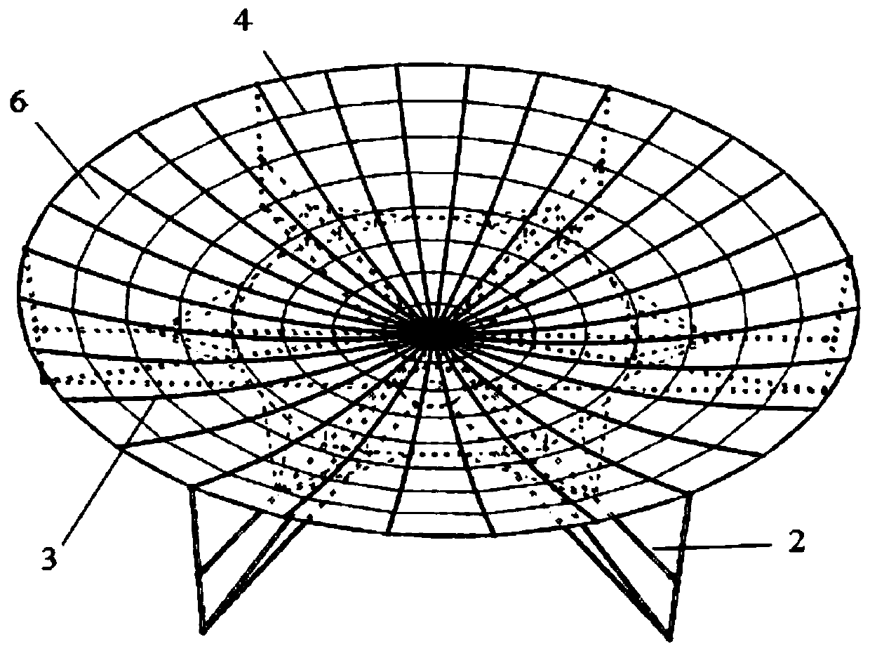
[0082] Elastic rib 3: uniformly hinged and arranged radially on the central faceplate node 1;
[0083] Deployable truss 2: one end is hinged to the central faceplate node 1, and the other end is slidingly connected to the elastic rib 3;
[0084] Multiple groups of hoop cables 4 arranged on the elastic ribs 3 from inside to outside: each group of hoop cables 4 is formed by connecting end-to-end flexible cable segments located between two adjacent elastic ribs 3;
[0085] Reverse tension array 5: connected between the elastic rib 3 and the deployable truss 2;
[0086] The reflective surface 6: is tensioned and laid on the grid structure formed by the elastic ribs 3 and the hoop cables 4.
[0087] see you again Figure 5-7 with Figure 10 As shown, the central faceplate node 1 is composed of an upper faceplate 1-1, a lo...
PUM
 Abstract
Description
Claims
Application Information
 - Generate Ideas
- Intellectual Property
- Life Sciences
- Materials
- Tech Scout
- Unparalleled Data Quality
- Higher Quality Content
- 60% Fewer Hallucinations
Browse by: Latest US Patents, China's latest patents, Technical Efficacy Thesaurus, Application Domain, Technology Topic, Popular Technical Reports.
© 2025 PatSnap. All rights reserved.Legal|Privacy policy|Modern Slavery Act Transparency Statement|Sitemap|About US| Contact US: help@patsnap.com