
Machining method for cycloid gear

A technology of cycloid gear and processing method, applied in the direction of elements with teeth, belt/chain/gear, gear teeth, etc., can solve the problems of difficult processing, low precision of tooth shape, complex shape, etc., to improve the precision of tooth shape and surface quality, saving processing costs and prolonging service life

Active Publication Date: 2016-06-15
XIAMEN UNIV OF TECH
View PDF8 Cites 6 Cited by
  • Summary
  • Abstract
  • Description
  • Claims
  • Application Information

AI Technical Summary

Problems solved by technology

The tooth surface of the cycloidal gear has high hardness and complex shape. At present, precision machining can only be processed by grinding technology, which is processed by a special cycloidal grinder.
Due to the special tooth shape of the cycloidal gear, the development relationship has the characteristics of planetary transmission, and the tooth profile of the cycloidal gear is often very small (especially the micro RV reducer for industrial robots), so the working conditions of the cycloidal grinding machine are harsh and difficult to process , the tooth shape accuracy and surface quality of the cycloidal gear after processing are poor, resulting in a greatly reduced transmission accuracy, transmission stability and reducer life of the cycloidal pin gear reducer
[0004] Therefore, in view of the defects of low tooth profile precision and poor surface quality in cycloidal gears currently processed by special grinding machines, the inventors conducted further research on this and developed a processing method for cycloidal gears, which resulted in this case

Method used


Image

  • Machining method for cycloid gear
  • Machining method for cycloid gear
  • Machining method for cycloid gear

Examples


Embodiment Construction

[0026] The present invention will be further described in detail below in conjunction with the accompanying drawings and specific embodiments.

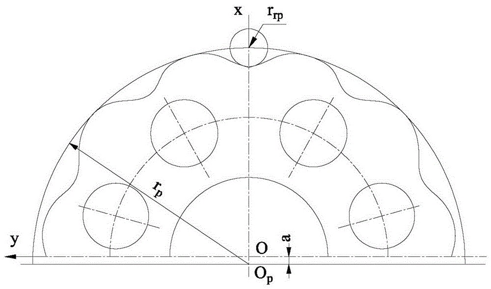
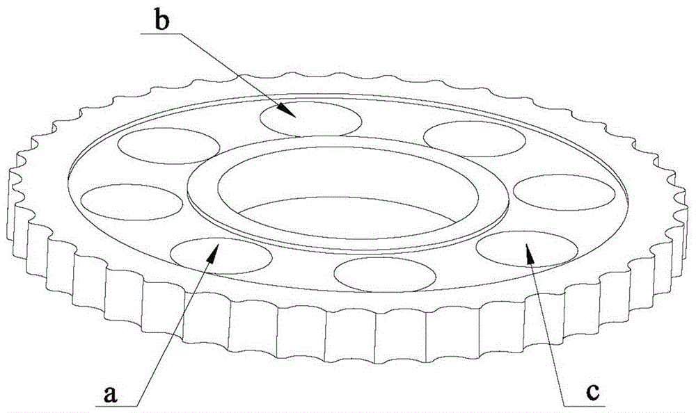
[0027] What the present invention discloses is a kind of processing method of cycloidal gear, such as figure 1 Shown, is the preferred embodiment of the present invention, at first, as image 3 As shown, the fine milling cycloidal gear finishing positioning datum holes a, b, c, in order to improve the positioning accuracy of the fine datum.

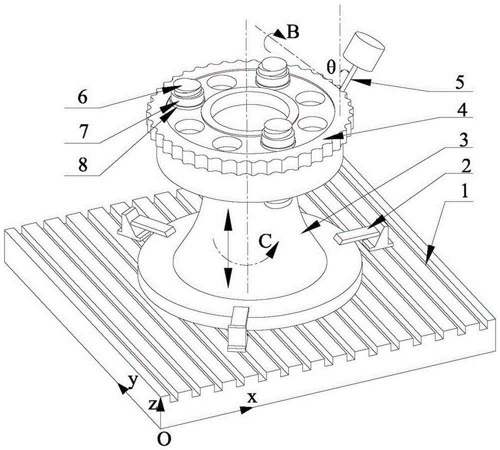
[0028] Such as figure 1 As shown, a cylindrical boss 3 is provided on the workbench 1 of the five-axis linkage CNC machine tool, and the cylindrical boss 3 is fixed on the workbench 1 through the clamp 2, and the pendulum is fixed by the stud bolt 6, the nut 7 and the washer 8. The wire gear 4 is clamped and positioned on the cylindrical boss 3 .

[0029] The probe of the five-axis CNC machine tool is used to determine the machining origin of the cycloidal gear 4 workpiece, and the five-axis l...


PUM


Abstract

The invention discloses a machining method for a cycloid gear. The machining method includes the following steps that a to-be-machined cycloid gear is fixed to a working table of a five-axis linkage numerical control machine tool; a flat bottom cutter is controlled by the five-axis linkage numerical control machine tool to rotate around the B axis of the five-axis linkage numerical control machine tool, so that the elevation of a cutter shaft of the flat bottom cutter is fixed to be theta, and the flat bottom cutter right faces the outline of the cycloid gear; the flat bottom cutter rotates at a high speed around the axis of the flat bottom cutter, and the cycloid gear starts to be machined and does vertical milling motion along the Z axis of the five-axis linkage numerical control machine tool along with the working table; and after walking through one track each time, the cycloid gear rotates around the C axis of the five-axis linkage numerical control machine tool along with the working table by a certain angle, and circulated machining is carried out until end milling of the overall gear is finished. According to the machining method, the gear shape accuracy and the surface quality of the cycloid gear can be effectively improved, burning generated during traditional grinding is avoided, and the problems in machining of the high-quality cycloid gear are solved.

Description

technical field [0001] The invention relates to the field of mechanical precision machining, in particular to a five-axis end milling finishing method for cycloidal gears. Background technique [0002] Cycloidal pinwheel reducers have many advantages such as high transmission efficiency, high speed ratio, high load capacity, and compact structure, and are widely used in mining, metallurgy, shipbuilding, and chemical industries. At present, the high-grade cycloid reducers used in large quantities in China are all dependent on imports, which not only increases the huge cost of related industries, but also seriously restricts the development of many important industries. At the same time, the backward situation of my country's robot manufacturing industry is largely due to the backward quality of related basic components, especially the micro RV cycloid reducer. [0003] The quality defects of the domestic cycloid reducer are mainly manifested in poor transmission accuracy, un...

Claims


Application Information

Patent Timeline
Patent Type & Authority Applications(China)
IPC IPC(8): B23F5/20
CPCB23F5/202
Inventor 罗善明廖龙兴王印王建易吉祥常雪峰
Owner XIAMEN UNIV OF TECH
Learn More